Photoreceptor, image forming method and image forming apparatus using the photoreceptor, process cartridge using the photoreceptor and coating liquid for the photoreceptor

a photoreceptor and image forming technology, applied in the field of electrophotographic photoreceptors, image forming methods and image forming apparatus, can solve the problems of difficult use of high-insulative materials, deterioration of density and quality of resultant images, and difficulty in high durability of small-diameter photoreceptors, so as to prevent an increase of residual potential or deterioration of images, and produce high-quality images stably

Active Publication Date: 2005-01-13
RICOH KK
View PDF87 Cites 78 Cited by
  • Summary
  • Abstract
  • Description
  • Claims
  • Application Information

AI Technical Summary

Benefits of technology

Accordingly, an object of the present invention is to provide an electrophotographic photoreceptor having high durability, preventing an increase of residual potential or deteriorated images due to occurrence of blurred images and stably producing high-quality images against repeated use for long periods.

Problems solved by technology

Photoreceptors using organic photosensitive materials are widely used for these laser printers and digital copiers due to their cost, productivity and non-polluting properties.
However, the photosensitive layers of the organic photoreceptor are easily abraded due to repeated use, and therefore potential and photosensitivity of the photoreceptor tend to deteriorate, resulting in background fouling due to a scratch on the surface thereof and deterioration of density and quality of the resultant images.
Therefore, the high-insulative is difficult to use and a low-insulative filler having relatively a small influence of residual potential is conventionally used, and means of equipping a drum heater heating a photoreceptor with an image forming apparatus is used against blurred images caused by the low-insulative filler.
Therefore, the drum heater cannot be applied to a photoreceptor having a small diameter which is now prevailing in accordance with downsizing of an electrophotographic apparatus, and high durability of a small-diameter photoreceptor is difficult.
Further, since an apparatus has to be large to be equipped with the drum heater, the electric power consumption remarkably increases and it takes much time to start the apparatus up, which are of many remaining subjects.
On the other hand, the residual potential increase when the high insulative filler is used causes a high potential of a light portion in an apparatus, resulting in deterioration of image density and tone reproduction.
In order to catch up this drawback, potential of a dark portion has to be increased and an electric intensity increases, resulting in not only defective images such as background fouling but also deterioration of a life of a photoreceptor.
However, since the protective layer absorbs light and amount of light reaching a photosensitive layer decreases, a problem that sensitivity of a photoreceptor deteriorates occurs, and an effect of the method is slight.
This method slightly prevents the increase of residual potential, but the effect is insufficient and does not solve the problem.
In addition, even when the filler has an average particle diameter not greater than 0.3 μm, the transparency deteriorates if the filler is agglutinated.
However, if the significant increase of residual potential caused by the filler is due to increase of resistance or charge trap caused by presence of the filler, the method has a limit to improve charge mobility and prevent the increase of residual potential.
Therefore, the thickness of the protective layer or the content of the filler has to be decreased, and the method does not satisfy required durability.
These methods decrease the residual potential, however, tend to cause blurred images and have a side effect of significantly affecting image quality.
In addition, when an organic acid is included in a protective layer, dispersibility of the filler tends to deteriorate and the effect is insufficient, and the methods do not solve the problem.
When a charge injected into the protective layer from a charge transport layer transfers to the surface, the charge is easily interrupted with the filler if the filler is agglutinated, resulting in dispersion of a dot formed of a toner and large deterioration of image resolution.
In addition, when light transmittance deteriorates because writing light is scattered by the filler, the image resolution is damaged as well.
Further, dispersibility of the filler largely influences abrasion resistance.
When the filler is firmly agglutinated and not well dispersed, the abrasion resistance largely deteriorates.
However, effective means to solve the problems at the same time are not found.
When a filler is included in the outermost surface of a photoreceptor, influences of the blurred images and increase of residual potential strongly appear and problems to attain high-quality images still remain.
In addition, this is a large bottleneck against downsizing the apparatus and decreasing the electric power consumption.
However, the electrophotographic photoreceptor produces lower quality images due a low resistance of the outermost surface although an increase of residual potential can be prevented and a dispersibility of the filler can be improved.

Method used


Image

  • Photoreceptor, image forming method and image forming apparatus using the photoreceptor, process cartridge using the photoreceptor and coating liquid for the photoreceptor
  • Photoreceptor, image forming method and image forming apparatus using the photoreceptor, process cartridge using the photoreceptor and coating liquid for the photoreceptor
  • Photoreceptor, image forming method and image forming apparatus using the photoreceptor, process cartridge using the photoreceptor and coating liquid for the photoreceptor

Examples


example 1

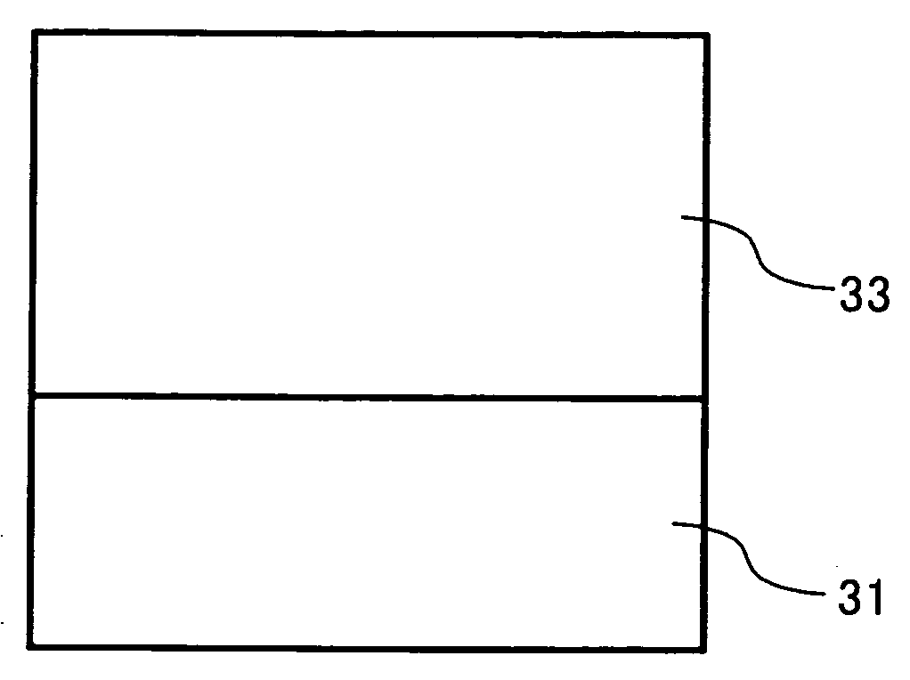
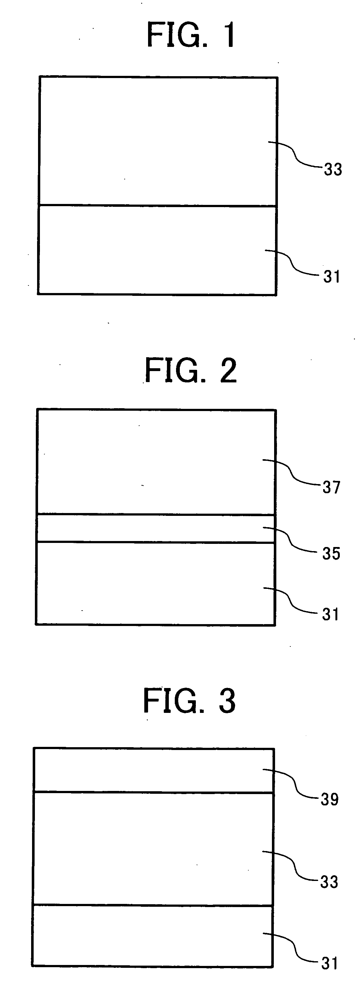
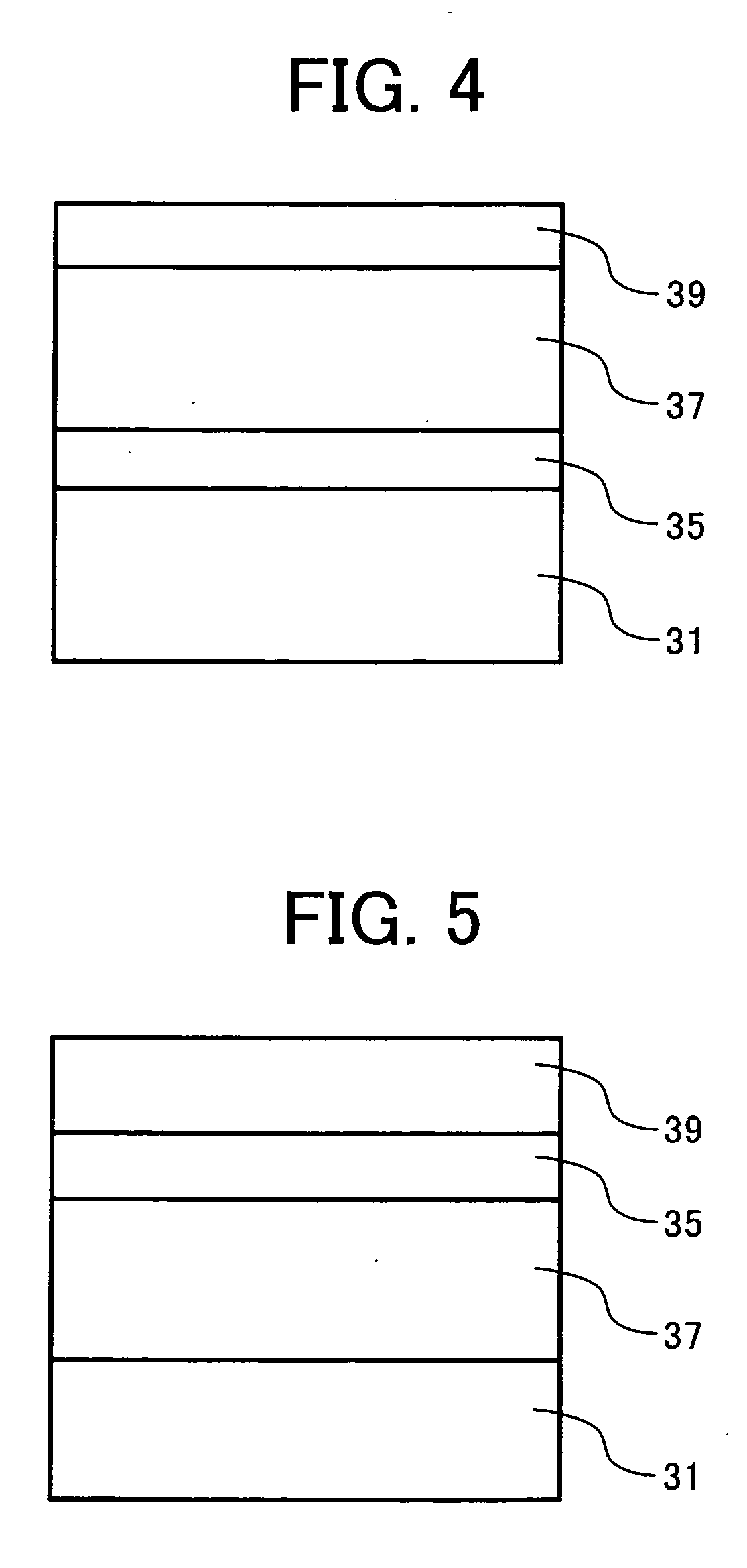
An undercoat coating liquid, a charge generation coating liquid and charge transport coating liquid, which have the following formulations, were coated in this order on an aluminium cylinder by a dip coating method and dried to prepare a photoreceptor 1 having an undercoat layer of 3.5 μm thick, a CGL of 0.2 μm thick, a CTL of 23 μm thick.

Undercoat Layer Coating Liquid

Titanium dioxide powder400Melamine resin65Alkyd resin1202-butanone400

CGL Coating Liquid

Fluorenone bisazo pigment12having the following formula:Polyvinyl butyral52-butanone200Cyclohexanone400

CTL Coating Liquid

Polycarbonate resin10(Z polyca from Teijin Chemicals Ltd.)CTM having the following formula:10Tetrahydrofuran100

A protective layer of 4 μm thick, having the following composition is further coated on the charge transport layer by a spray coating method to prepare an electrophotographic photoreceptor 1.

Protective Layer Coating Liquid

Alumina (AA-03 ® having an average2primary particle diameter of 0.3 μ...

example 2

The procedure for preparation of the electrophotographic photoreceptor in Example 1 was repeated except that the unsaturated polycarboxylate polymer included in the protective layer was changed to the following material to prepare an electrophotographic photoreceptor 2.

Unsaturated polycarboxylate polymer0.02(BYK-P105 ® having an acid value of365 mg KOH / g from BYK Chemie Co., Ltd.)

example 3

The procedure for preparation of the electrophotographic photoreceptor in Example 1 was repeated except that the unsaturated polycarboxylate polymer included in the protective layer was changed to the following material to prepare an electrophotographic photoreceptor 3.

Polyester resin (having an acid value0.2of 35 mg KOH / g)


PUM


Abstract

A photoreceptor including an electroconductive substrate; a photosensitive layer; and optionally a protective layer, wherein an outermost layer thereof includes a filler, an organic compound having an acid value of from 10 to 700 mg KOH/g and at least one compound selected from the group consisting of compounds having the following formulae (1) and (2):
wherein R1 (R3) and R2 (R4) independently represent a substituted or an unsubstituted aromatic hydrocarbon group, or a substituted or an unsubstituted alkyl group, and optionally share bond connectivity to form a heterocyclic group including a nitrogen atom; Ar1 (Ar3) and Ar2 (Ar4) independently represent a substituted or a unsubstituted aromatic ring group; k (K) and m (M) independently represent 0 or an integer of from 1 to 3, wherein k (K) and m (M) are not 0 at the same time; and n (n′) represents an integer of from 1 to 3.

Description

BACKGROUND OF THE INVENTION 1. Field of the Invention The present invention relates to an electrophotographic photoreceptor, an image forming method and an image forming apparatus using the electrophotographic photoreceptor, a process cartridge for image forming apparatus using the electrophotographic photoreceptor, and a coating liquid for the electrophotographic photoreceptor. 2. Discussion of the Background Recently, information-processing systems using an electrophotographic method are making a remarkable progress. In particular, laser printers and digital copiers which record data with light by changing the data into digital signals make remarkable improvements in their printing qualities and reliabilities. Further, technologies used in these printers and copiers are applied to laser printers and digital copiers capable of printing full-color images with high-speed printing technologies. Because of these reasons, photoreceptors are required both to produce high-quality imag...

Claims


Application Information

Patent Timeline
Patent Type & Authority Applications(United States)
IPC IPC(8): G03G5/05G03G5/06G03G5/147
CPCG03G5/051G03G5/0521G03G5/0614G03G5/14708G03G5/0672G03G5/0674G03G5/0661G03G5/061473G03G5/06144G03G5/06147G03G5/061446
Inventor IKEGAMI, TAKAAKISHIMADA, TOMOYUKISUZUKI, YASUOTAMOTO, NOZOMUKAMI, HIDETOSHITAKANA, YUUJI
Owner RICOH KK
Why Eureka
Try Eureka