Acoustic condition sensor employing a plurality of mutually non-orthogonal waves

a plurality of mutually non-orthogonal waves and condition sensors, applied in the field of acoustic touch position sensors, can solve the problems of limited touch characteristic information, large shadowing area in which two-dimensional touch positions cannot be reconstructed, and limited versatility in shape and size, so as to reduce noise or separate potentially interfering waveforms, enhance performance, and differ sensitivity

Inactive Publication Date: 2005-01-20
ELO TOUCH SOLUTIONS INC
View PDF27 Cites 80 Cited by
  • Summary
  • Abstract
  • Description
  • Claims
  • Application Information

AI Technical Summary

Benefits of technology

Sensor systems according to the present invention allow superposition of waves producing sets of touch-sensitive waves which are dispersed across the touch area of the substrate having characteristic time delays or other characteristics, and a system for receiving the dispersed waves and determining a characteristic of a touch or wave perturbation. The axes of propagation of one set of waves need not be orthogonal to those of another set. According to the present invention, these sets of non-orthogonal waves may be employed with orthogonal waves. By providing more than one set of these plurality of waves, a position of a touch may be determined using redundant information, e.g., having more information than is necessary to mathematically determine a position, allowing enhanced performance in the presence of noise, interference and shadowing.
As stated above, the acoustic waves may differ in other properties, including mode, propagation velocity, wavelength, which in general provides two advantages. First, waves having differing properties may have differing sensitivity to environmental conditions and artifacts. Thus, the differential effect on the sensing waves may be used to determine properties of an object in contact with the surface. Further, the differences in the waves may be used to selectively filter the waves, thus providing opportunity to selectively reduce noise or separate potentially interfering waveforms. Waves having differing wavelength in the substrate may be selectively redirected with reflective arrays having physical characteristics corresponding to that wavelength and its axis of propagation.

Problems solved by technology

First, acoustically absorptive contamination in localized regions, e.g. a water drop on a known Rayleigh-wave sensor, result in large areas of shadowing in which two-dimensional touch positions cannot be reconstructed.
Second, the configurational requirements of these sensors limits their versatility with regard to shape and size.
Third, reconstruction of touch coordinates may lead to ambiguities when more than one touch is applied simultaneously.
Finally, such sensors provide limited touch characteristic information from which to differentiate valid touches from false touches, e.g. fingers from water drops.
In contrast, few if any touchscreen products are presently available for applications in which the touchscreen is an input device that is intended to be used by more than one user simultaneously.
However, the basic principles of acoustic touchscreen operation are largely independent of the choice of acoustic mode.
Thus, users coming out of the rain or snow with wet clothes, gloves or umbrellas are likely to leave occasional drops of water on the touchscreen surface.
However, a cover sheet generally reduces the optical quality of the displayed image seen through the resulting sensor and leads to a less durable exposed surface.
These waves, however, also have reduced sensitivity, resulting in either reduced touch sensitivity of the touch system, increased susceptibility to electromagnetic interference, or more expensive controller circuitry.
The increased bulk of a sensor designed for low-frequency Rayleigh waves is typically a serious mechanical design problem.
These thin substrates are fragile, and Lamb waves have energy on both top and bottom surfaces, making optical bonding problematic due to signal damping.
Further, ZOHPS waves support limited options for optical bonding, such as RTVs (silicone rubbers) which do not support shear radiation damping.
Shear waves have reduced sensitivity compared to Rayleigh waves thus making detection of gloved fingers more difficult.
Secondly, in such climates, drops of water may freeze to form solid ice.
Thus drops of water which freeze on the touchscreen surface will cause shadowing or blinding.
At present, no commercial electronic whiteboard products are available based on acoustic sensor technology.
In part, this is because of size limitations for known acoustic technology.

Method used


Image

  • Acoustic condition sensor employing a plurality of mutually non-orthogonal waves
  • Acoustic condition sensor employing a plurality of mutually non-orthogonal waves
  • Acoustic condition sensor employing a plurality of mutually non-orthogonal waves

Examples


example 1

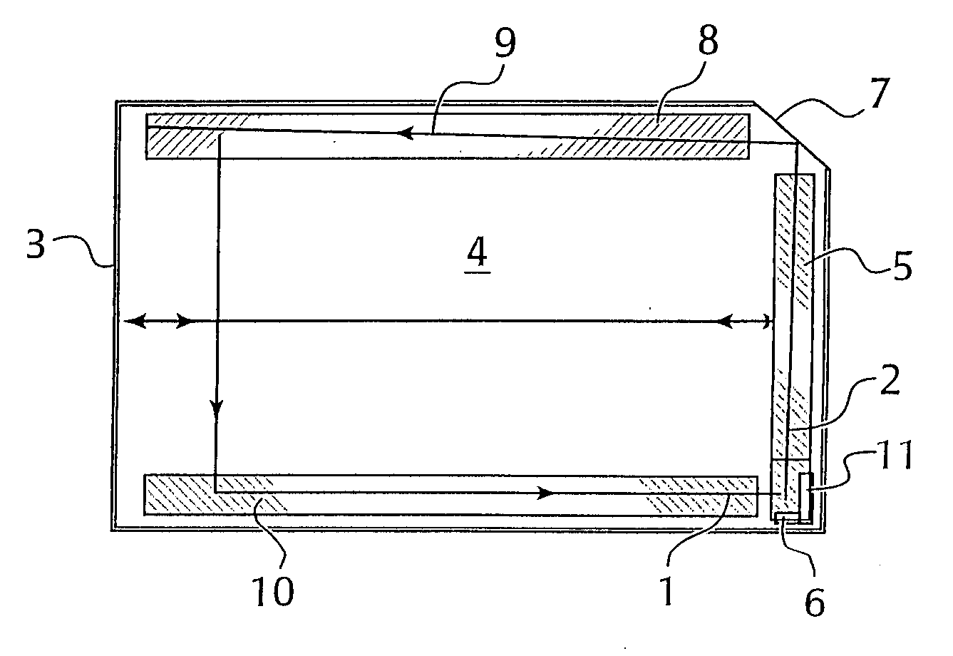
FIG. 10 represents a generic sensor subsystem including transmit and receive transducers and arrays. This generic sensor subsystem includes a family of embodiments which differ in the various parameters.

Later examples will generalize to families of embodiments in which the acoustic path between the transmit and receive arrays are scattered one or more times by reflective boundaries. Later examples will also generalize to families of embodiments in which the sensor surface has non-planar geometry. In this example, we consider the generic sensor subsystem of FIG. 10.

In the embodiment of FIG. 10, a set of acoustic paths is associated with a sensor subsystem. Each member of the set of acoustic paths can be represented by a value between zero and one of a path parameter “s”. (In cases where a range other than zero to one is mathematically convenient; this can easily be accommodated with a change of variables.) The acoustic path for a given path parameter starts at the transmit transd...

example 2

FIG. 12 illustrates examples of specific touch region geometries within the scope of FIG. 10.

The rectangular touch region shown in FIG. 12(a) is typical of the X-coordinate sensor subsystems of current flat rectangular acoustic touchscreen products.

If all segments of the acoustic path in FIG. 12(a) use the same acoustic mode, then the spacing-vector formula leads to the prior art 45° reflectors with wavelength spacing along the array axes. For example, if the incident wave is in the −X direction and the scattered wave is in the Y direction, then the spacing vector is calculated to be S=(nλ / 2,nλ / 2) and hence the reflectors are at 45° the spacing between reflectors in a direction perpendicular to the reflectors is nλ / {square root}2 and the reflector spacing in along the array axis nλ.

If, instead, the transmit and receive array modes are zeroth order horizontally polarized shear (ZOHPS) waves and the touch region mode is a Lamb wave, then the spacing vector is calculated to be S=...

example 3

FIG. 13 represents an example sensor design that utilizes four sensor subsystems. This design supports control systems which include anti-shadowing algorithms and algorithms that resolve multi-touch ambiguities. The touch region has a width-to-height aspect ratio of {square root}3:1.

Two sensor subsystems are rectangular as in FIG. 12(a); see FIG. 13(a). By itself, FIG. 13(a) has much in common with prior art sensors with standard X and Y measurements. FIG. 13(a) shows an X transmit transducer 1301, an X transmit reflective array 1302, with reflective elements at 45°, an X receive reflective array 1303, with reflective elements at 45°, and an X receive transducer 1304. Likewise, a Y transmit transducer 1305, a Y transmit reflective array 1306, with reflective elements at 45°, a Y receive reflective array 1307, with reflective elements at 45°, and a Y receive transducer 1308 is provided along an orthogonal set of axes.

The other two subsystems provide a measurement of a “U” diagona...


PUM


Abstract

A touch sensor comprising an acoustic wave transmissive medium having a surface; a plurality of acoustic wave path forming systems, each generating a set of incrementally varying paths through said transmissive medium; and a receiver, receiving signals representing said sets of waves, a portion of each set overlapping temporally or physically by propagating in said transmissive medium along axes which are not orthogonal. The waves may also be of differing wave modes. The receiver system may include a phase, waveform or amplitude sensitive system. Reflective arrays are associated with said medium situated along a path, said path not being a linear segment parallel to a coordinate axis of a substrate in a Cartesian space, a segment parallel to an axial axis or perpendicular to a radial axis of a substrate in a cylindrical space, nor parallel and adjacent to a side of a rectangular region of a small solid angle section of a sphere; situated along a path substantially not corresponding to a desired coordinate axis of a touch position output signal; situated along a path substantially non-parallel to an edge of said medium; has a spacing of elements in said array which differs, over at least one portion thereof, from an integral multiple of a wavelength of an incident acoustic wave; has elements in said array which are non-parallel; has an angle of acceptance of acoustic waves which varies over regions of said array; and/or coherently scatter at least two distinguishable acoustic waves which are received by said receiving system.

Description

TECHNICAL FIELD OF THE INVENTION The present invention relates to an acoustic touch position sensor, and more particularly to such a sensor wherein a coordinate position, and optionally an absorption characteristic, of an acoustic disturbance is determined by analyzing a plurality of received signals. The present invention allows the sensing system to employ waves to differ in path geometry, and / or wave characteristic type, e.g., mode, frequency, waveform, velocity, and / or wavelength. This system advantageously allows redundant position measurement and / or differential wave perturbation sensing. BACKGROUND OF THE INVENTION Acoustic touch position sensors are well known. A common system includes two sets of transducers, each set having a different axis aligned respectively with the axes of a physical Cartesian coordinate system defined by a substrate. An acoustic pulse is generated by one transducer, propagating as a Rayleigh wave along an axis which intersects an array of reflectiv...

Claims


Application Information

Patent Timeline
Patent Type & Authority Applications(United States)
IPC IPC(8): G08C21/00G06F3/033G06F3/041G06F3/043G06F3/0488H01H35/00
CPCG06F3/0418H03K2217/96011G06F3/0436Y10S367/907G08C25/00
Inventor KENT, JOEL
Owner ELO TOUCH SOLUTIONS INC
Why Eureka
Try Eureka