
Acoustic transducer

Inactive Publication Date: 2005-01-27
HORIBA LTD
View PDF26 Cites 16 Cited by
  • Summary
  • Abstract
  • Description
  • Claims
  • Application Information

AI Technical Summary

Benefits of technology

In carrying out the present invention, an acoustic transducer for measuring a property of a fluid is provided. The acoustic transducer comprises an acoustic pulse generator and a buffer assembly. The buffer assembly is located between the pulse generator and the fluid. The buffer assembly is composed of a core and a sleeve shrink fitted over the core to form a cladding. The cladding reduces dispersion of the acoustic pulses traveling through the core.
The acoustic pulse generator may be a piezoceramic element for generating an ultrasonic pulse. Preferably, the core thermal conductivity is less than 15 W / (m·K). More preferably, the core thermal conductivity is less than 1 W / (m·K). The core may be made of fused silica, and is preferably made of a composite of fused silica and mica. Of course, ceramics or other materials may alternatively be used for the core. By making the core of a light weight, low thermal conductivity material that is more corrosion resistant than the body of the transducer, a metallic sealing layer is not needed and the core may be in direct contact with the fluid which is being measured or have a light anti-reflective surface coating.
The sleeve may be made of metal, and preferably has a thermal conductivity of at least 15 W / (m·K). In a preferred implementation, the sleeve is made of titanium. It is appreciated that the sleeve is shrink fitted over the core to form a cladding. The cladding reduces dispersion of the acoustic pulses traveling through the core. The shrink fitting of the sleeve over the core to form the cladding has advantages over other possible techniques to form a cladding such as spray deposition or powder metallurgy. Using the mechanical technique of shrink fitting provides a suitable cladded core at great cost savings relative to other possible techniques. In accordance with the invention, preferred techniques for securing the sleeve to the core include using a refractory cement and using high temperature glass fusing. The cladding provides the needed gradient in longitudinal sound speed through a medium to reduce dispersion of acoustic pulses traveling through the core.
The advantages associated with embodiments of the present invention are numerous. For example, preferred embodiments of the present invention provide an acoustic transducer by shrink fitting a coaxial metal sleeve over a core of low thermal conductivity material. The cladding reduces dispersion of the acoustic pulse traveling through the core.

Problems solved by technology

However, these ceramics lose polarization if exposed to temperatures in excess of half of their Curie point.
A disadvantage associated with existing buffer systems is that a short buffer has problems when operating with hot fluids, while making the buffer longer requires that the buffer guide the wave front in the desired direction.
However, solid buffers fail to effectively guide the acoustic pulse resulting in a dispersive buffer that distorts the ultrasonic pulse and limits the usefulness of the flow meter.
However, the doping techniques used to create the cladding have some disadvantages.

Method used


Image

  • Acoustic transducer
  • Acoustic transducer
  • Acoustic transducer

Examples


Embodiment Construction

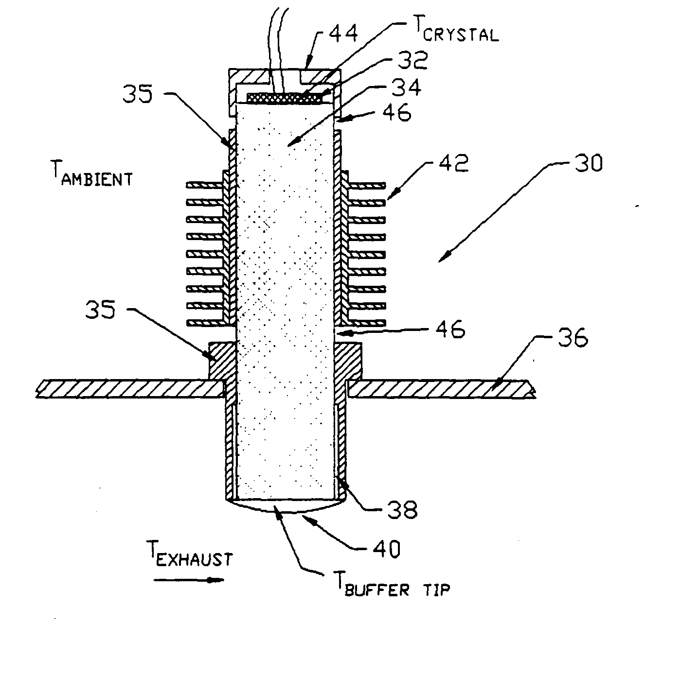
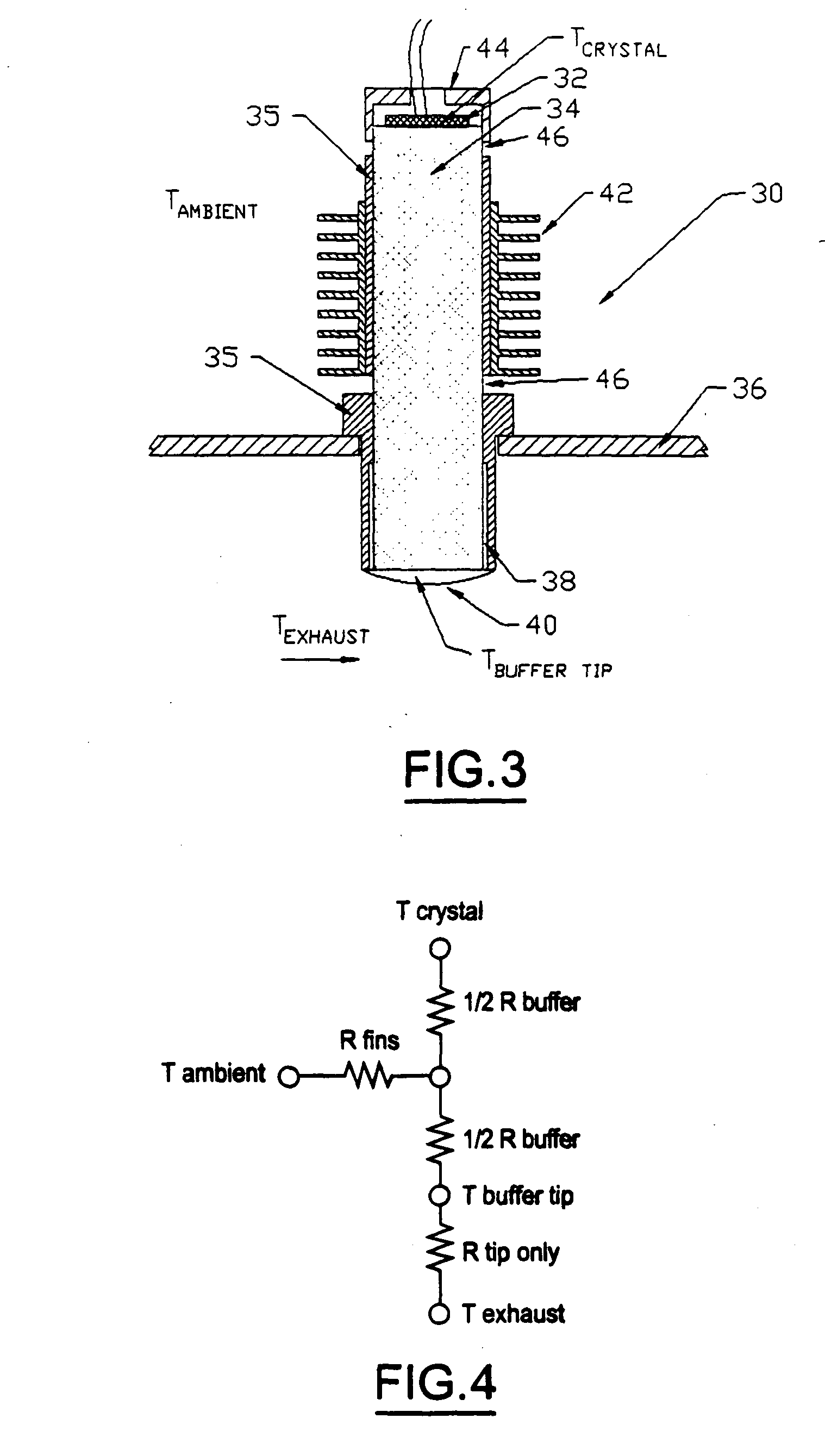
FIG. 3 illustrates an acoustic transducer 30 for measuring a property of a fluid. Transducer 30 includes piezoelectric element 32, and a buffer assembly composed of a core 34 and a sleeve 35. Sleeve 35 is shrink fitted over core 34 to form a cladding that reduces dispersion of the acoustic pulses traveling through core 34. The buffer assembly extends through wall 36 of a conduit through which the fluid flows. The conduit is part of an apparatus in which the acoustic transducer 30 is used. Buffer core 34 is made of a light weight, low thermal conductivity material and is preferably composed of fused silica and mica. Sleeve 35 is made of titanium and extends through wall 36 to form a metal shield 38 with a small air gap between it and the core 34 to form a high contact resistance in comparison to convective thermal boundary layer 40. The metal shield 38 also protects the buffer during installation and operation. The buffer tip is in direct contact with the fluid but could have a surfa...


PUM


Abstract

An acoustic transducer for measuring a property of a fluid includes an acoustic pulse generator and buffer assembly. The buffer assembly is between the pulse generator and the fluid. The buffer assembly is composed of a core and a sleeve shrink fitted over the core to form a cladding layer. The cladding layer reduces dispersion of the acoustic pulses traveling through the core.

Description

BACKGROUND OF THE INVENTION 1. Field of the Invention The present invention relates to acoustic transducers, including those used in flow meters. 2. Background Art Transmitting pulses of acoustic energy through a fluid is useful for measuring the state and properties of the fluid, specifically the velocity and temperature. Piezoceramic elements are commonly used in acoustic transducers to generate ultrasonic acoustic pulses or continuous wave fields. However, these ceramics lose polarization if exposed to temperatures in excess of half of their Curie point. For commercially available ceramics, this limits the operating temperature of the ceramic to under 200° C. To operate in fluids above this temperature, one method is to provide a buffer or delay line between the piezoceramic element and the fluid (for example, exhaust gas) as shown in FIG. 1. FIG. 1 depicts an acoustic transducer 10. Transducer 10 includes piezoceramic element 12 and buffer 14 extending through wall 16 into t...

Claims


Application Information

Patent Timeline
IPC IPC(8): B06B1/06G01N29/02G01N29/22G01N29/28
CPCB06B1/067G01F1/662G01N2291/02836G01N29/222G01N29/28G01N29/02B06B1/06G01F1/667G01N29/2468
Inventor HILL, JAMES A.
Owner HORIBA LTD
Features
  • Generate Ideas
  • Intellectual Property
  • Life Sciences
  • Materials
  • Tech Scout
  • Unparalleled Data Quality
  • Higher Quality Content
  • 60% Fewer Hallucinations
Learn More