Colorable microspheres for DNA and protein microarray

a protein microarray and colorable technology, applied in the field of biological microarray technology, can solve the problems of high manufacturing cost, high method cost, and limitations, and achieve the effects of increasing the number of target analytes, expanding the “spectral bar coding” capacity of the microsphere, and reducing the cost of methods

Inactive Publication Date: 2005-01-27
CARESTREAM HEALTH INC
View PDF14 Cites 15 Cited by
  • Summary
  • Abstract
  • Description
  • Claims
  • Application Information

AI Technical Summary

Benefits of technology

The present invention includes several advantages, not all of which are incorporated in a single embodiment. In one advantage, the microsphere of the present invention may overcome one particular problem associated with “spectrally addressed microspheres”, wherein the colored compounds typically used in the microspheres are often fluorescent, and hence will provide excessive “background noise” when fluorimetric determinations are performed on the microarray. This problem can be overcome through the use of latent colorants, which are colorless and relatively non-emissive until “switched” to a colored state by a chemical reaction, a physical trigger, or some kind of environmental stimulus. In another advantage, the use of latent colorant significantly expands the “spectral bar coding” capacity of the microsphere which allows a large number of diversity of microspheres to be generated. Thus, a single array can afford to measure increased number of target analytes in a single experiment. In another advantage of the present invention, the colorless coding offers no detectable background fluorescence from microspheres, therefore the limit of detection is dramatically improved. As such, another advantage is that the microarray prepared according to the present invention also provide a broad dynamic range for measurement of target analytes.

Problems solved by technology

This method is expensive.
An ink jet approach is being used by others (e.g., U.S. Pat. Nos. 6,079,283; 6,083,762; and 6,094,966) to fabricate spatially addressable arrays, but this technique also suffers from high manufacturing cost in addition to the relatively large spot size of 40 to 100 μm.
While that invention provides a huge manufacturing advantage over then existing technologies, it presents some limitations as well.
However, such approach suffers two problems: (1) the colorant itself emits fluorescence that interferes with the fluorescence signal resulting from the biological interaction; (2) when the adsorption wavelength of the barcoding dye is complementary to the biological interaction fluorescence emission, the fluorescence signal intensity is significantly suppressed.
Problem 1 severely limits the color barcoding diversity of the microspheres, and problem 2 dramatically reduces the dynamic range and low detection limit of the microarray system.

Method used


Image

  • Colorable microspheres for DNA and protein microarray
  • Colorable microspheres for DNA and protein microarray
  • Colorable microspheres for DNA and protein microarray

Examples


example 1

This examples illustrates two methods of loading photographic couplers as latent colorants into polystyrene microspheres.

Loading method 1: For a typical preparation, a microsphere sample was prepared using a single coupler, or a fixed ratio of more than one couplers, and different ratios of coupler, coupler solvent, and auxiliary coupler solvent. The cyan coupler CYAN 1 was loaded using the sonication method as follows: 0.08 g CYAN 1 was dissolved in 0.8 g cyclohexanone and 0.08 g tricresolphosphate with stirring. This oil phase was then added to an aqueous phase of 0.48 g FAC-0064 (surfactant) and 6.52 g water with stirring at room temperature. The sample was sonicated for 1 min, producing a milky white dispersion, and then let stir. An equivalent amount, 8.0 g, of 4% 1 0-micron polystyrene microspheres was added to the sonicated sample. After mixing, the samples were poured into diafiltration bags and washed for six hours. After the diafiltration, the microspheres loaded with c...

example 2

These examples illustrate a method of loading photographic couplers as latent colorants into polystyrene microspheres using in situ polymerization process.

TABLE 1Monomer-coupler 1Monomer-coupler 2Monomer-coupler 3(cyan)(yellow)(magenta)

TABLE 2Reagents used in the preparation of beads containing monomer-boundcouplers and characterization data.Bead #1 (cyan)2 (yellow)3 (magenta)Monomer-0.85——coupler 1 (g)Monomer-—0.85—coupler 2 (g)Monomer-——0.85coupler 3 (g)Styrene (ml)36.636.636.6AIBN (g)0.380.380.38Ethanol (ml)87.587.587.5Methyl125.0125.0125.0cellosolve(ml)Polyacrylic3.753.753.75acid (g)Mean4.264.927.54particlediameter(μm)

Beads 1-3, containing cyan, magenta, and yellow couplers (Couplers 1-3) respectively, were all synthesized by the same procedure using the reagents and quantities listed in Table 2. Polyacrylic acid (3.75 g, Mw=450K) was dissolved in 67.5 ml absolute ethanol in a 500 ml 3-neck round bottom flask equipped with a nitrogen inlet, mechanical stirrer, and reflux con...

example 3

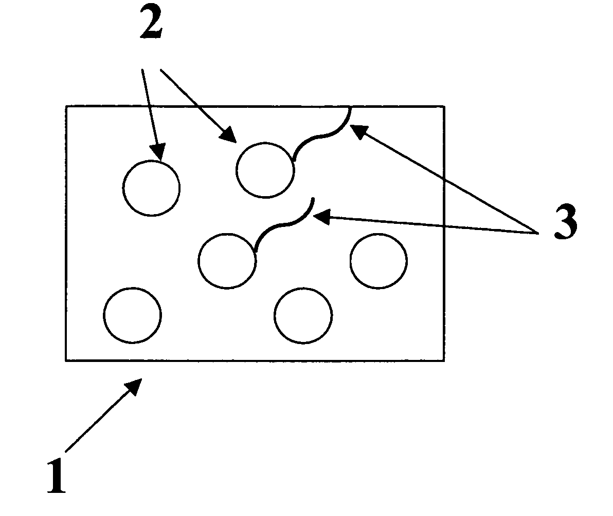
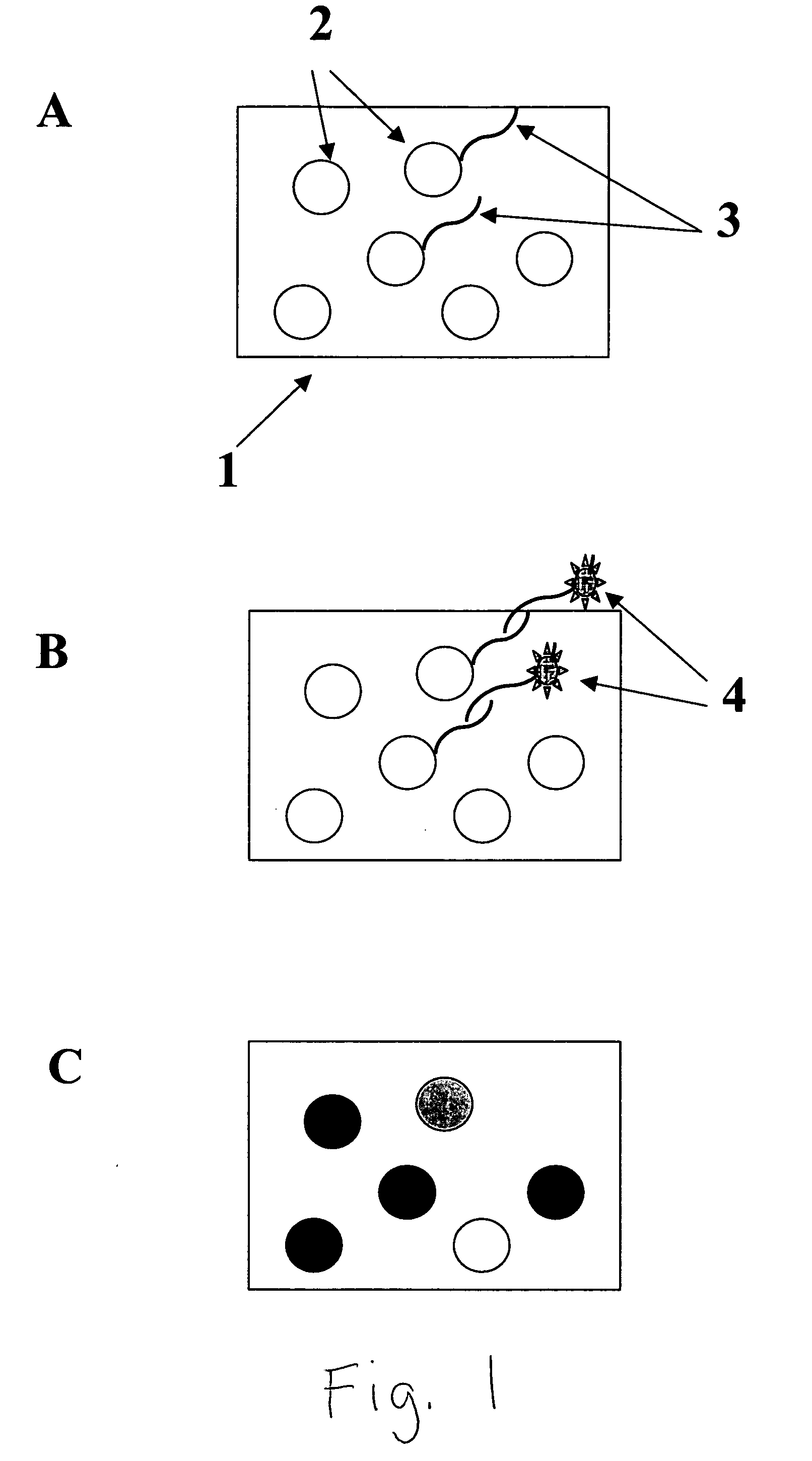
This example illustrates the attachment of pre-synthesized single strand oligonucleotide probe to the surface of coupler incorporated microspheres.

One hundred microliters of coupler incorporated microspheres (4% w / v) was rinsed three times in acetate buffer (0.01 M, pH5.0), and combined with one hundred microliters of 20 mM 2-(4-Dimethylcarbomoyl-pyridino)-ethane-1-sulfonate and ten percent of polyethyleneimine. The mixture was agitated at room temperature for one hour and rinsed three times with sodium boric buffer (0.05 M, pH8.3). The beads were re-suspended in sodium boric buffer.

An oligonucleotide DNA probe with 5′-amino-C6 modification was dissolved in one hundred microliters of sodium boric buffer to a final concentration of 40 nmol. A 20 microliters of cyanuric chloride in acetonitril was added to the DNA probe solution and the total volume was brought up to 250 microliter using sodium boric buffer. The solution was agitated at room temperature for one hour and then dial...


PUM

PropertyMeasurementUnit
mean diameteraaaaaaaaaa
affinity binding constantaaaaaaaaaa

Abstract

A microarray comprising: a support, on which is disposed a layer of microspheres bearing biological probes; wherein said microspheres comprise at least one material with a latent color that can be developed and used to identify said microsphere. A method of identifying biological analytes using the microarray is also disclosed.

Description

FIELD OF THE INVENTION The present invention concerns biological microarray technology in general. In particular, it concerns an array of microspheres immobilized on a substrate and a method of exposing the surface of the microspheres to analytes contained in test samples. The microspheres contain latent colorants that identify the microspheres when the color is switched on. The microspheres also bear capture agents (also called probes) on their surfaces. BACKGROUND OF THE INVENTION Current technologies have used various approaches to fabricate microarrays. For example, U.S. Pat. Nos. 5,143,854, 5,412,087, and 5,489,678 demonstrate the use of a photolithographic process for making peptide and DNA microarrays. The patent teaches the use of photolabile protecting groups to prepare peptide and DNA microarrays through successive cycles of deprotecting a defined spot on a 1 cm×1 cm chip by photolithography, then flooding the entire surface with an activated amino acid or DNA base. Repe...

Claims


Application Information

Patent Timeline
Patent Type & Authority Applications(United States)
IPC IPC(8): B01J19/00G01N33/543G01N33/58
CPCB01J19/0046B01J2219/00466B01J2219/00545B01J2219/00576B01J2219/00648B01J2219/00659G01N33/583B01J2219/00722B01J2219/00725B01J2219/00731G01N33/54313G01N33/54386B01J2219/0072
Inventor QIAO, TIECHENG A.LEON, JEFFREY W.SCHROEDER, KURT M.
Owner CARESTREAM HEALTH INC
Why Eureka
Try Eureka