SOI device with reduced drain induced barrier lowering

a technology of drain induced barrier and soi device, which is applied in the direction of cmos device, semiconductor device, electrical apparatus, etc., can solve the problems of reducing the channel length of the cmos device, causing performance drawbacks, and often creating performance drawbacks, so as to reduce the dibl effect and reduce the floating body effect.

Inactive Publication Date: 2005-01-27
MICRON TECH INC
View PDF16 Cites 2 Cited by
  • Summary
  • Abstract
  • Description
  • Claims
  • Application Information

AI Technical Summary

Benefits of technology

[0013] Another aspect of the invention comprises dopant atoms implanted through the device regions such that the dopant atoms come to reside within the Buried OXide (BOX) layer underlying the device regions creating a borophosphosilicate glass (BPSG) within the BOX layer. Formation of the passivation layer causes the dopant atoms contained within the BPSG to diffuse into the device regions so as to create the retrograde dopant profile in the device regions. The retrograde dopant profile has a peak concentration substantially adjacent the interface of the BOX and the active region. The retrograde dopant profile in the device region provides the transistor device with improved resistance to drain-induced barrier lowering (DIBL) and also provides the transistor device with recombination centers to reduce floating body effects.
[0015] In another aspect of the invention, formation of the passivation layer induces the dopant atoms contained within the BPSG to outdiffuse into the device regions thereby forming a retrograde dopant profile within the device regions. The retrograde dopant profile within the device regions reduces DIBL effects for the CMOS device and also provides recombination centers adjacent the BOX active region interface thereby reducing floating body effects. These and other objects and advantages of the present invention will become more fully apparent from the following description taken in conjunction with the accompanying drawings.

Problems solved by technology

However, scaling often creates some performance drawbacks.
In particular, a known category of performance limitations known as short channel effects arise as the length of the channel of CMOS devices is reduced by scaling.
However in some applications, such as in an SOI process, it is difficult to create a retrograde profile due to the thinness of the silicon layer and the tendency of the dopants to diffuse.
Increasing the Si film thickness any further will increase the extent to which the devices formed therein get partially depleted.
SOI devices also suffer from ‘floating body’ effects since, unlike conventional CMOS, in SOI there is no known easy way to form a contact to the bulk in order to remove the bulk charges.
In SOI, since the silicon film is very thin, creating a true retrograde dopant profile is very difficult.

Method used


Image

  • SOI device with reduced drain induced barrier lowering
  • SOI device with reduced drain induced barrier lowering
  • SOI device with reduced drain induced barrier lowering

Examples


Embodiment Construction

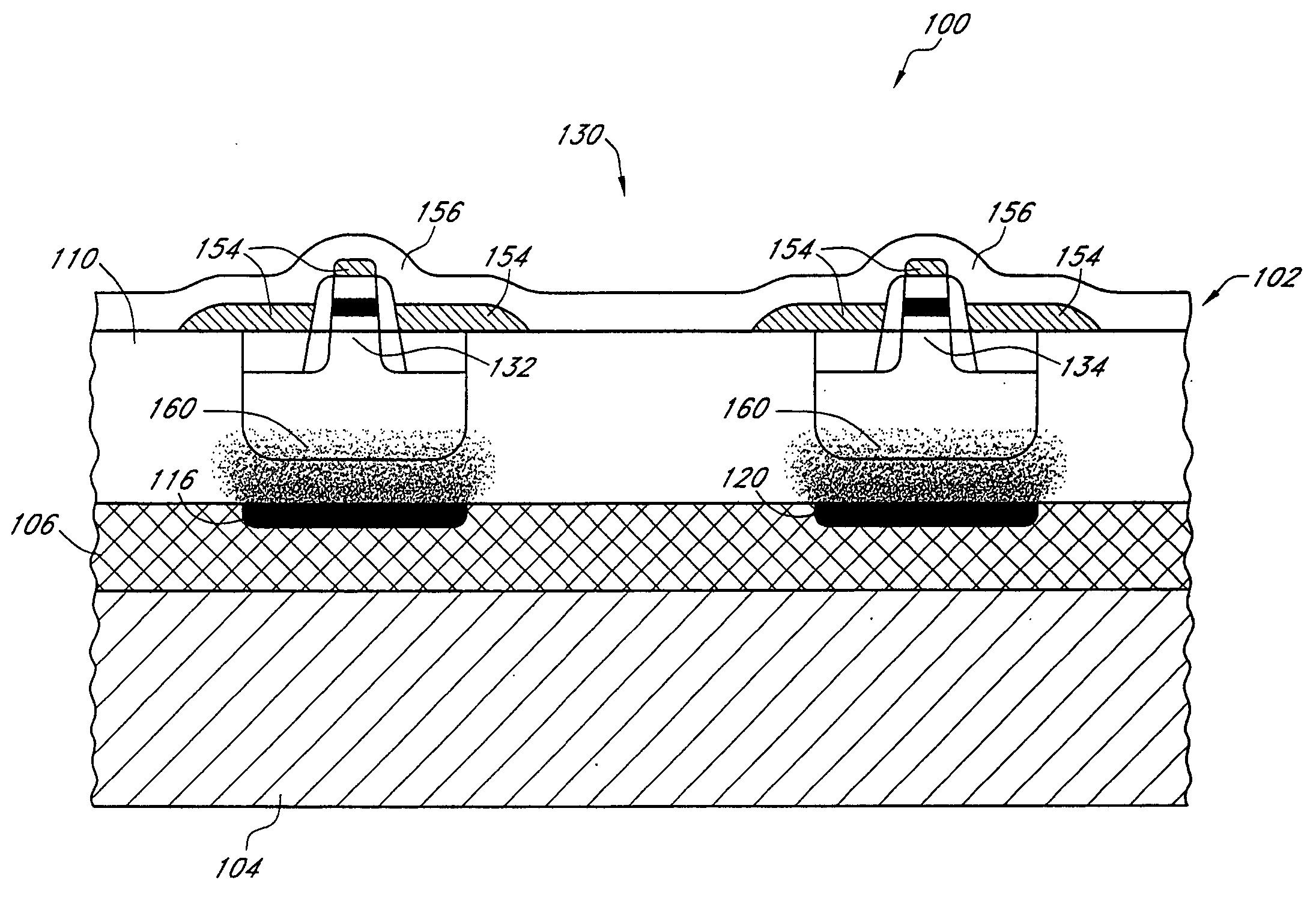
[0025] Reference will now be made to the drawings wherein like numerals refer to like structures throughout. FIG. 4 is a section view of one embodiment of the SOI CMOS with reduced DIBL 100 of the present invention showing the starting SOI material, a Separation by IMplanted OXygen (SIMOX) wafer 102. The SIMOX wafer 102 is well known in the art and comprises a silicon substrate 104 in which a layer of the substrate 104 is converted to a buried silicon dioxide (BOX) 106 layer with a heavy oxygen implant and subsequent anneal. An epitaxial layer 110 of Si approximately 500 Å to 2500 Å thick is then grown on top of the BOX layer 106. The BOX layer 106 of the SIMOX wafer 102 provides electrical insulation between the active region of the epitaxial layer 110 and the bulk silicon of the substrate 104. Thus, active devices formed in the epitaxial layer 110 are electrically isolated from the semiconductive substrate 104. The SIMOX wafer 102 also provides physical structure as well as reacti...


PUM

PropertyMeasurementUnit
temperatureaaaaaaaaaa
concentrationaaaaaaaaaa

Abstract

A CMOS device formed with a Silicon On Insulator (SOI) technology with reduced Drain Induced Barrier Lowering (DIBL) characteristics and a method for producing the same. The method involves a high energy, high dose implant of boron and phosphorus through the p- and n-wells, into the insulator layer, thereby creating a borophosphosilicate glass (BPSG) structure within the insulation layer underlying the p- and n-wells of the SOI wafer. Backend high temperature processing steps induce diffusion of the boron and phosphorus contained in the BPSG into the p- and n-wells, thereby forming a retrograde dopant profile in the wells. The retrograde dopant profile reduces DIBL and also provides recombination centers adjacent the insulator layer and the active layer to thereby reduce floating body effects for the CMOS device.

Description

RELATED APPLICATIONS [0001] This application is a continuation of U.S. patent application Ser. No. 10 / 747,586, filed Dec. 29, 2003, entitled “SOI DEVICE WITH REDUCED DRAIN INDUCED BARRIER LOWERING” which is a continuation of U.S. patent application Ser. No. 10 / 268,578, filed Oct. 10, 2002, entitled “SOI CMOS DEVICE WITH REDUCED DIBL” (now U.S. Pat. No. 6,716,682) which is a continuation of U.S. patent application Ser. No. 09 / 652,864, filed Aug. 31, 2000, entitled “SOI CMOS DEVICE WITH REDUCED DIBL” (now U.S. Pat. No. 6,503,783).BACKGROUND OF THE INVENTION [0002] 1. Field of the Invention [0003] The present invention relates to the field of semiconductor devices and fabrication processes and, in particular, to CMOS devices formed in a silicon-on-insulator (SOI) technology with reduced drain induced barrier lowering (DIBL) and a method for fabricating the same. [0004] 2. Description of the Related Art [0005] There is an ever-present desire in the semiconductor fabrication industry to ...

Claims


Application Information

Patent Timeline
Patent Type & Authority Applications(United States)
IPC IPC(8): H01L21/84H01L27/12
CPCH01L21/26513H01L21/26533H01L21/84H01L29/7833H01L29/1083H01L29/665H01L27/1203H01L21/2658
Inventor MOULI, CHANDRA V.
Owner MICRON TECH INC
Why Eureka
Try Eureka