

Rapid flow-based immunoassay microchip
a flow-based immunoassay and microchip technology, applied in the field of rapid flow-based immunoassay microchips, can solve the problems of long incubation time of conventional clinical immunoassays, large quantity of expensive reagents, and large available devices, and achieve the effect of rapid analysis
- Summary
- Abstract
- Description
- Claims
- Application Information
AI Technical Summary
Benefits of technology
Problems solved by technology
Method used
Image

Examples
example 1
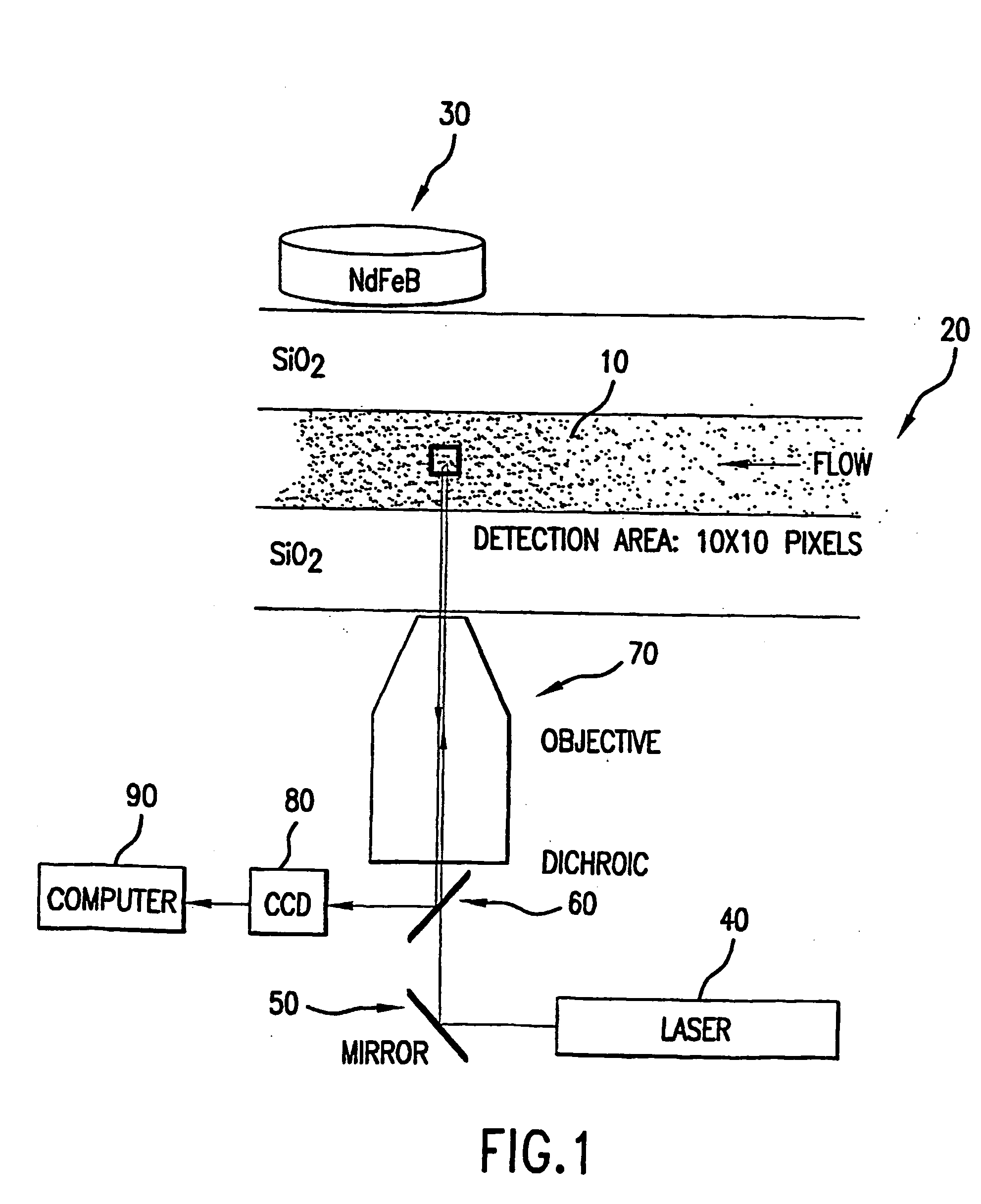
[0031] Vacuum induced pressures provided the fluidic transport within this experiment. The paramagnetic beads were typically packed under 0.33 atm vacuum for 30 seconds, followed by a 0.101 atm vacuum for 2 minutes. This provided a uniformly packed bed of approximately 1-2 mm in length (given 50.8 cm capillary length, 50 μm inner diameter). Once introduced into the microchannels, the paramagnetic beads were locally restrained by the application of a magnetic field. A rare earth magnet used to generate the external field is a ¾″ diameter, 0.1875″ thick disk of NdFeB (27 / 30 mixed), rated at 11 lbs. lift (Edmund Scientific, Barrington, N.J.; Cat. Number: CR35-106). Previously labeled anti-FITC paramagnetic beads were packed for a total bed length of 1-2 mm. Fluorescence was monitored before FITC introduction into the microchannel, during the FITC interaction, and after a buffer wash following FITC exposure using laser induced fluorescence. The optical train for this experimental proced...
example 2
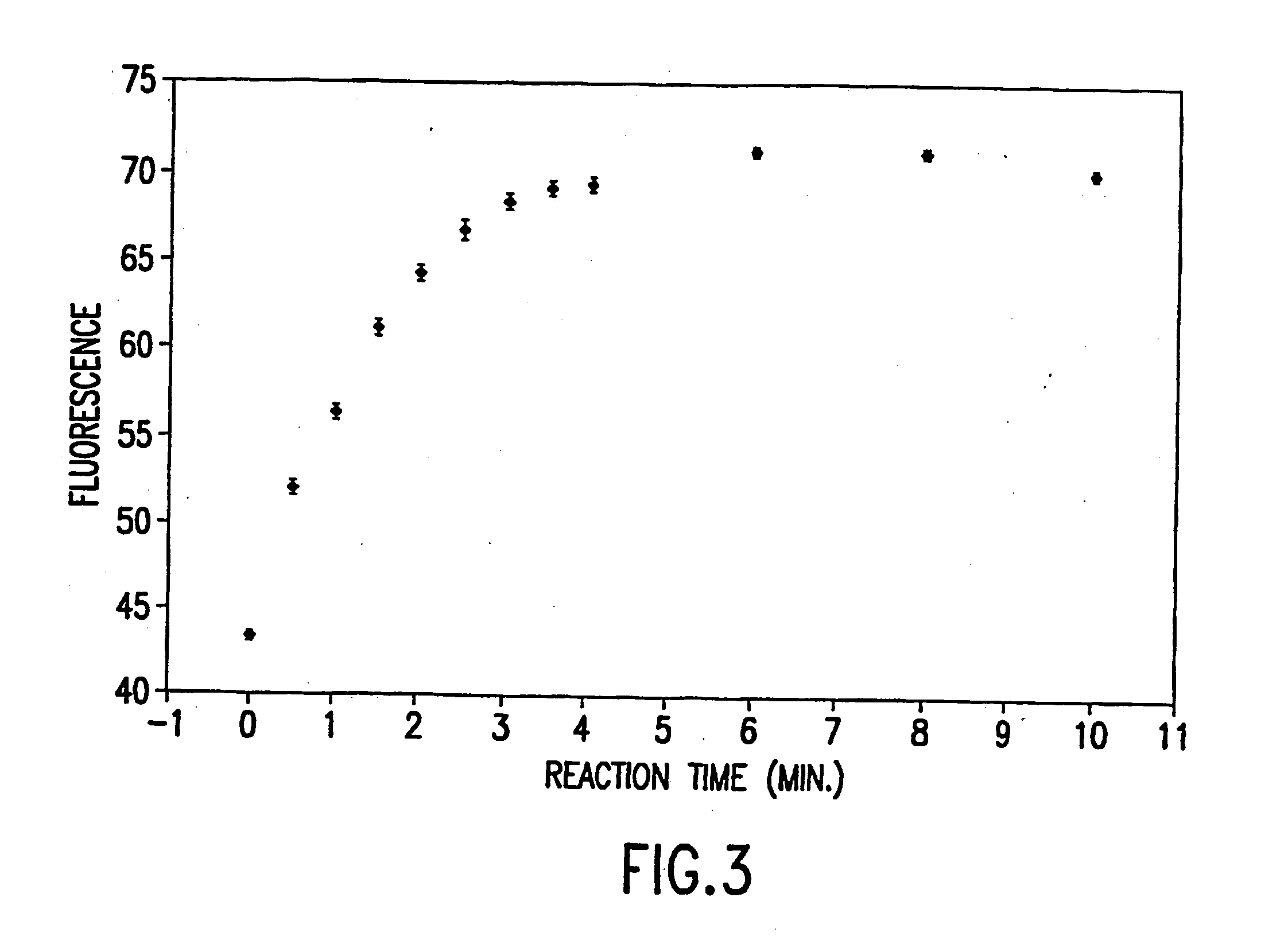
[0033] To validate the microimmunoassay system, initial control experiments were done to discount any increase in fluorescence due to non-specific binding. Primary antibody was loaded onto the 1-2 μm diameter paramagnetic beads. A 360 μm o.d. / 50 μm i.d. fused silica capillary (50.8 cm length) was used for this experiment. The beads were introduced into the capillaries by applying 0.33 atm vacuum to a counter reservoir for 30 seconds followed by 0.101 atm vacuum for 2 minutes. Buffer was then flushed through the system for 10 minutes to allow for system equilibrium. A neodymium-iron-boron (NdFeB) magnet was placed over the capillary prior to introduction of the beads to ensure the formation of a packed bed. Two initial experiments were performed, one using paramagnetic beads labeled with monoclonal anti-FITC antibody, and the other with non-labeled paramagnetic beads. After the bed was packed 1 mM FITC was flushed through the bed for 15 minutes followed by a buffer rinse to remove fr...
example 3
[0035] A bed regeneration experiment was performed following Example 2. In this experiment, buffer was washed over the paramagnetic beads labeled with anti-FITC (same bed conditions as reaction time studies) after 125 μm FITC was exposed to the bed for 10 minutes where laser induced fluorescence was monitored over time as shown in FIG. 4. Approximately one hour after the buffer wash was initiated, the packed bed fluorescence has decreased to within 35% of background levels. After approximately two hours, the fluorescence has decreased to within 16%, and after three hours, the fluorescence signal is within 5% of background fluorescence levels.
PUM
| Property | Measurement | Unit |
|---|---|---|
| Magnetic field | aaaaa | aaaaa |
| Fluorescence | aaaaa | aaaaa |
| Paramagnetism | aaaaa | aaaaa |
Abstract
Description
Claims
Application Information