
Method of making an implantable medical device

a medical device and implantable technology, applied in the field of implantable medical devices surface features, can solve the problems of occlusion of conduits, affecting and intimal flaps or torn arterial linings that can collapse, and achieve the effect of enhancing the delivery of therapeutic substances and high retention

Inactive Publication Date: 2005-02-10
ABBOTT CARDIOVASCULAR
View PDF90 Cites 101 Cited by
  • Summary
  • Abstract
  • Description
  • Claims
  • Application Information

AI Technical Summary

Benefits of technology

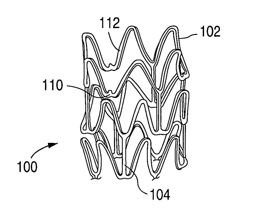
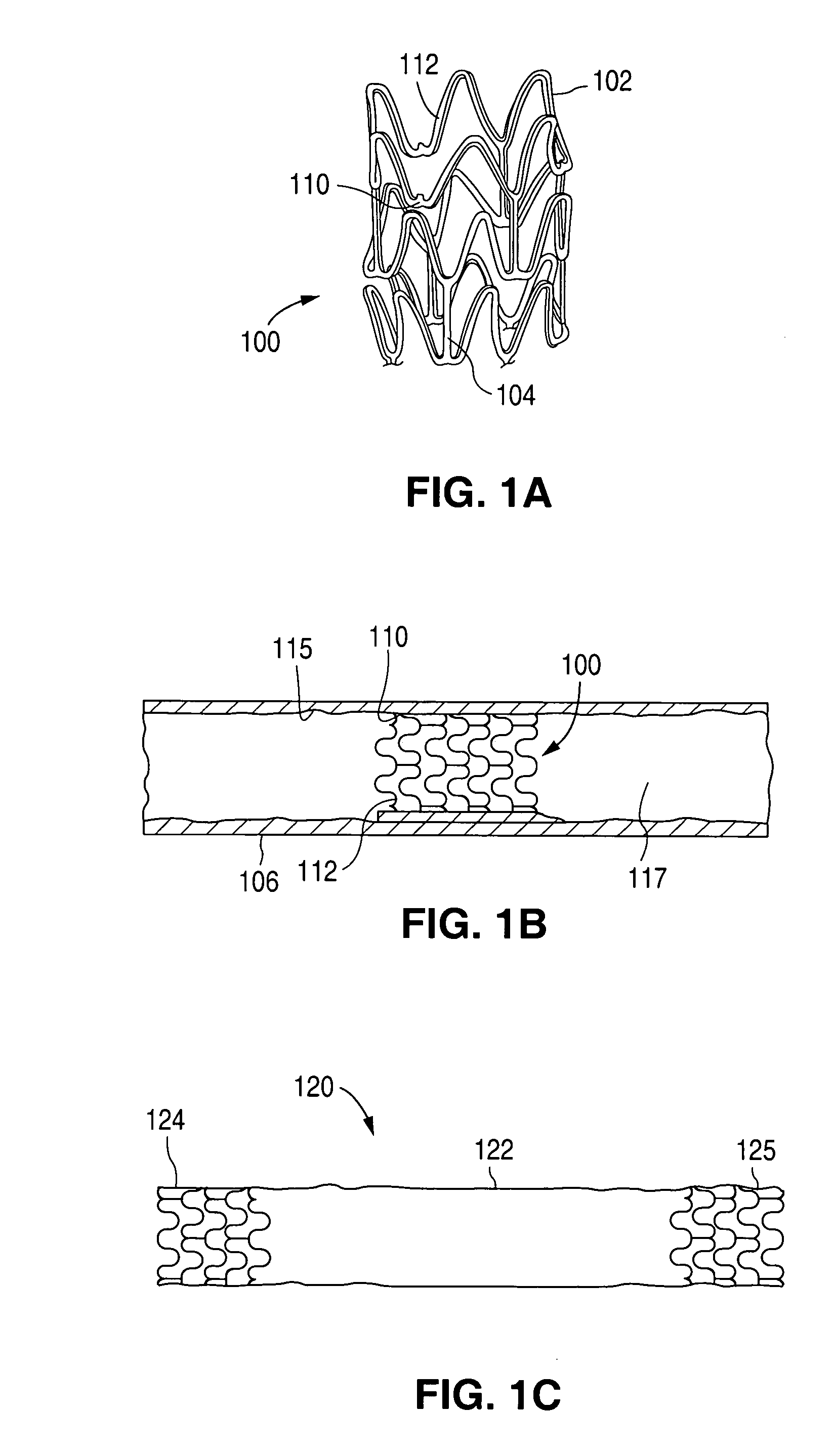
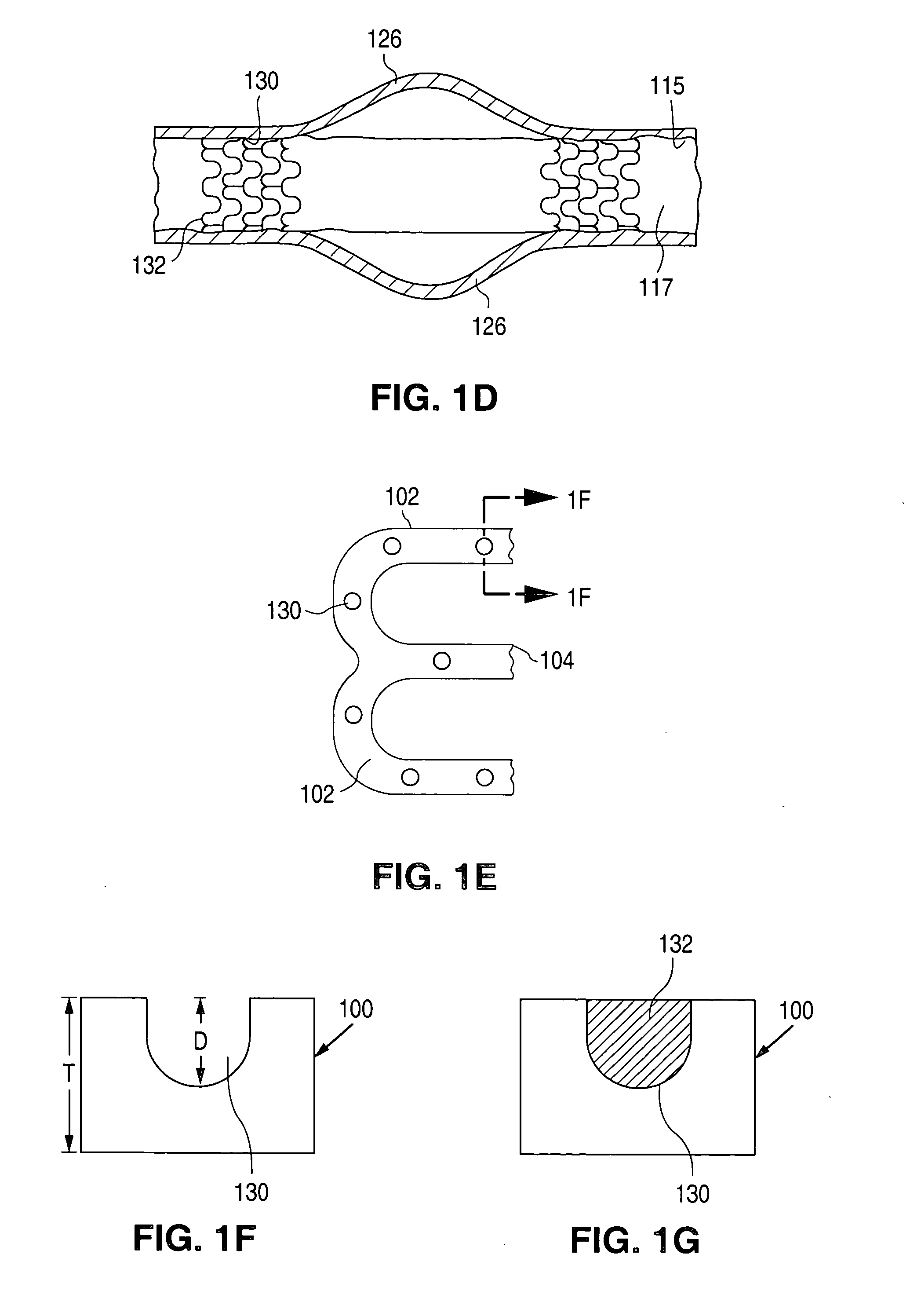
An implantable medical device capable of delivering therapeutic substances from a coating is provided, which provides a high retention of one or more layers of coating material. The implantable device also allows a greater total amount of coating to be carried by the device, allowing for greater amounts of therapeutic substances to be delivered from the device. In some embodiments the implantable device can penetrate the arterial wall to enhance delivery of therapeutic substances into the arterial wall.

Problems solved by technology

A problem associated with the procedure includes formation of intimal flaps or torn arterial linings that can collapse and occlude the conduit after the balloon is deflated.
A problem encountered with intravascular stents is that, once implanted into the blood stream, platelets and other blood components tend to adhere to any portion of the stent surfaces having roughness or irregularity.
Adhesion and aggregation of platelets and other blood components can lead to thrombosis and restenosis.
To provide an efficacious concentration to the treated site, systemic administration of these drugs often produces adverse or toxic side effects for the patient.
An obstacle often encountered with the use of stent coatings is poor adhesion of the polymeric coating to the surface of a stent.
Also, when a coated stent is expanded in situ, the distortion the stent undergoes as it expands can cause the coating to peel, crack, or tear, and disengage from the stent.
Poor adhesion of the coating material can promote thrombosis and restenosis, by providing additional surfaces for platelets and other blood components to adhere.
Additionally, poor adhesion and loss of the coating also leads to loss of a significant amount of the drugs to be delivered from the coating.
Another technical challenge in using stent coatings to deliver drugs is loading enough drug onto the stent, so that an effective amount of the drug or drug combination is delivered to the treatment site.
However, increasing the thickness of a stent coating can be difficult, particularly if the coating does not adhere well to the stent material.
However, additional layers tend to adhere poorly to underlying layers.
Another complication for drug delivery from a stent is that the arterial wall tissue the stent is compressed against can be tough and fibrotic, preventing medication released from the stent from penetrating the tissue in which the medication may be therapeutically beneficial.

Method used


Image

  • Method of making an implantable medical device
  • Method of making an implantable medical device
  • Method of making an implantable medical device

Examples


example

Stents # 1-5 were fabricated by cutting, descaling, and polishing a 316L stainless steel hypo-tube as described in U.S. Pat. No. 5,759,192 . The inner surface of stents # 1-#4 were protected by inserting a mandrel, hypotube, or inflated balloon into the interior of the stent to protect the inner surface. The outer surface of each stent was bead blasted, using bead diameters in the range of 10 μm to 50 μm. Stents #1 and #2 were bead blasted at 60 PSI pressure and stents #3 and #4 were bead blasted at 30 PSI pressure, as indicated in Table 1. Bead blasting was done at a distance of approximately 5 cm from the stent. The beads were passed very quickly, in approximately 1-3 seconds, down and up over the stent outer surface. The stent was then rotated 120° and the process repeated twice so the entire stent was roughened. After bead blasting, stents # 1-# 4 were cleaned by immersion in an ultrasonic isopropyl alcohol bath for 20 minutes and allowed to dry. Stent #5 was also cleaned in an...


PUM


Abstract

An implantable medical device, such as a stent or graft, having asperities on a designated region of its outer surface is disclosed. The asperities can serve to improve retention of one or more layers of a coating on the device and to increase the amount of coating that can be carried by the device. The asperities can be formed by using a stream of pressurized grit to roughen the surface. The asperities can also be formed by removing material from the outer surface, for example, by chemical etching with or without a patterned mask. Alternatively, the asperities can be formed by adding material to the outer surface, for example, by welding powder particles to the outer surface or sputtering.

Description

BACKGROUND OF THE INVENTION 1. Field of the Invention This invention relates to surface features of implantable medical devices, for example stents and grafts, and to methods for forming such surface features. 2. Description of the Background Percutaneous transluminal coronary angioplasty (PTCA) is a procedure for treating heart disease. A catheter assembly having a balloon portion is introduced into the cardiovascular system of a patient via the brachial or femoral artery. The catheter assembly is advanced through the coronary vasculature until the balloon portion is positioned across the occlusive lesion. Once in position across the lesion, the balloon is inflated to a predetermined size to radially compress against and remodel the artery wall for dilating the lumen. The balloon is then deflated to a smaller profile to allow the catheter to be withdrawn from the patient's vasculature. A problem associated with the procedure includes formation of intimal flaps or torn arterial...

Claims


Application Information

Patent Timeline
Patent Type & Authority Applications(United States)
IPC IPC(8): A61F2/00A61F2/06A61F2/90
CPCA61F2/0077A61F2/848A61F2/91A61F2/915A61F2230/0013A61F2250/0067A61F2250/0068Y10S623/901A61F2002/91533
Inventor WU, STEVEN Z.HARISH, SAMEERSANDERS-MILLARE, DEBORRAGURUWAIYA, JUDY A.MIRZAEE, DARYUSHHOSSAINY, SYEDCHEN, CHARLENE
Owner ABBOTT CARDIOVASCULAR
Learn More