

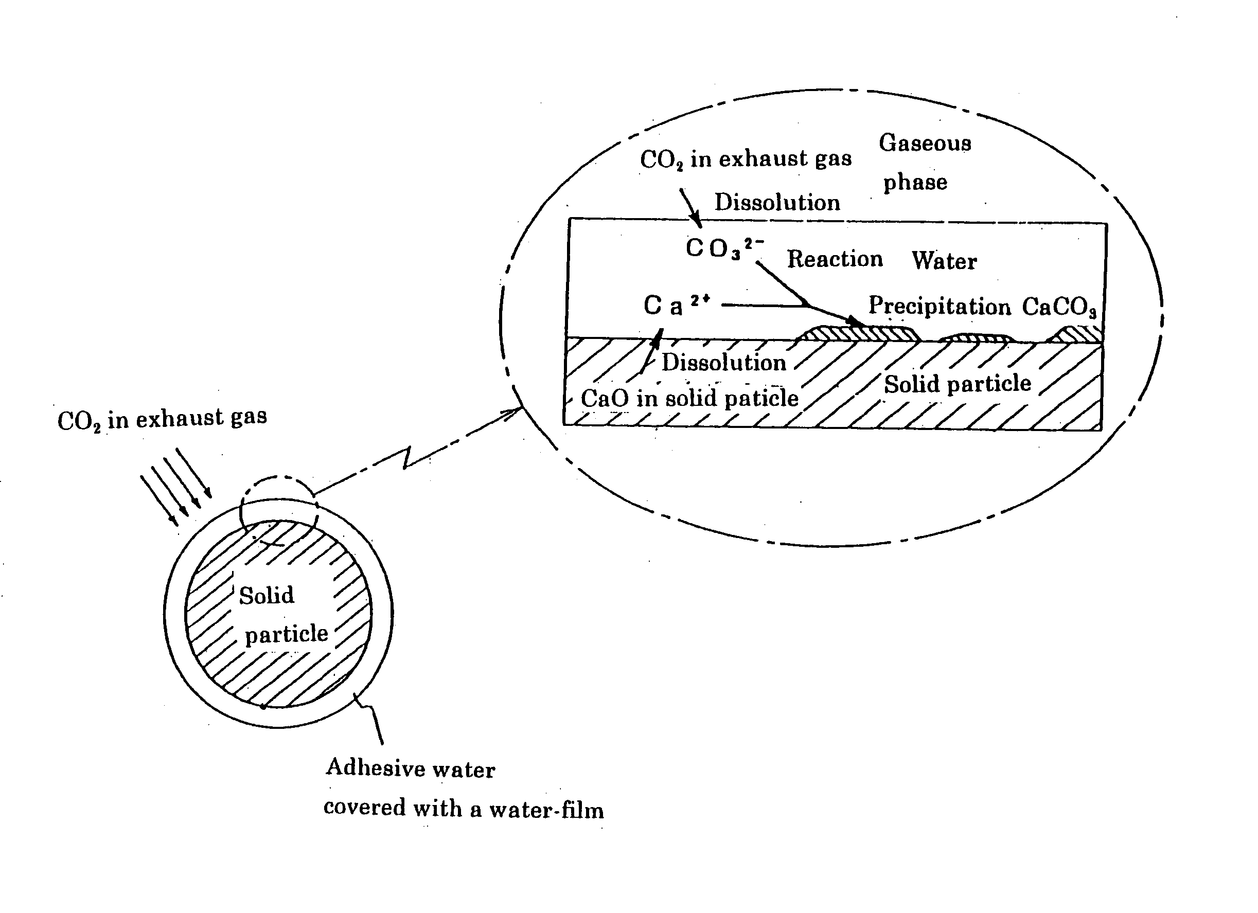
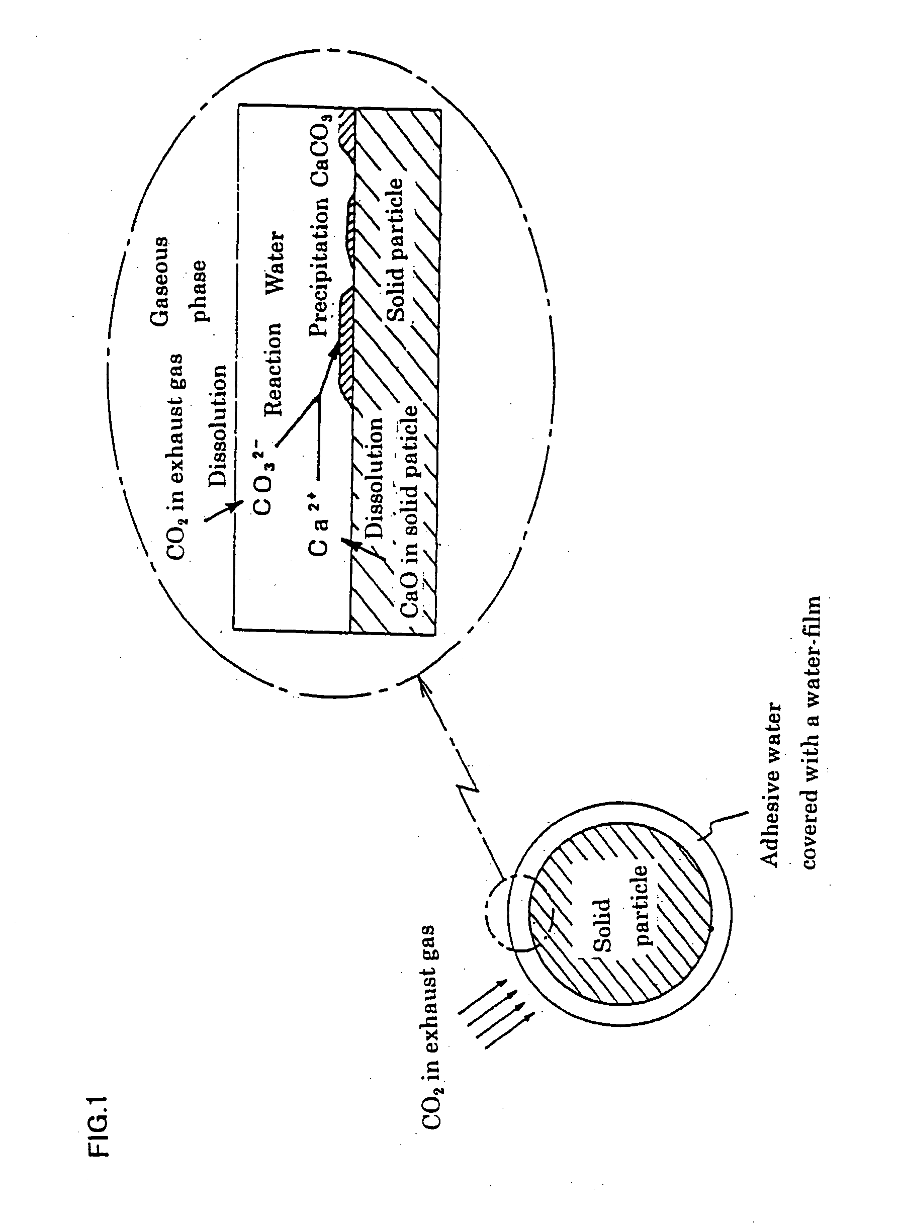
Method for reducing exhaust carbon dioxide
a technology of exhaust carbon dioxide and exhaust gas, which is applied in the direction of magnesium compounds, plant cultivation, separation processes, etc., can solve the problems of inconvenient the inability to achieve the target of cutting co2 only with the control of the amount of energy used, and the ineffective method of removing co2 from exhaust gas on an industrial scale is not yet conventionally known. , to achieve the effect of reducing the amount of exhausting co2, effective absorption and
- Summary
- Abstract
- Description
- Claims
- Application Information
AI Technical Summary
Benefits of technology
Problems solved by technology
Method used
Image

Examples
example 1
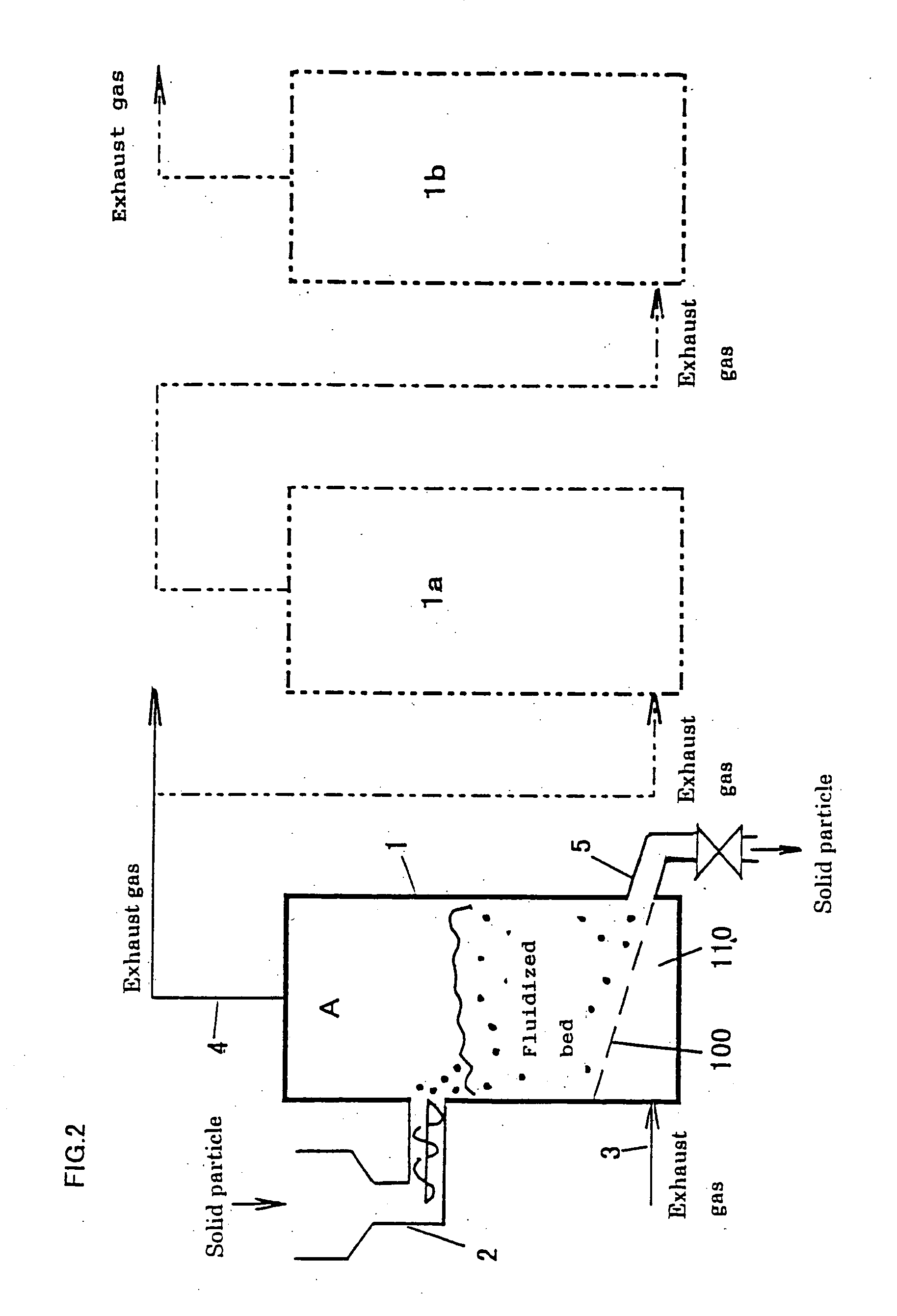
[0164] A pipe shaped reactor of 2 m length having an inlet and an outlet for the exhaust gas at both ends was filled with the slag (grain size: 10 mm or lower, CaO: 35 wt. %, water content: 6%, packing ratio: 50 vol. %) . The packed bed was supplied with the exhaust gas (CO2 concentration: 20%, temperature: 40° C.) at the gas pressure: 0.3 kgf / cm2-G for 24 hours, and as a result of measuring the CO2 absorbing amount by the slag, the absorbed CO2 was about 0.2 at value of CO2 / slag.
[0165] Being based on this CO2 absorbing amount, when the CO2 absorbing amount in a real machine was calculated by trial, the calculation meant that it was possible to absorb CO2 of 15,000 t / year (in terms of C), using 200,000 t / year of slag.
example 2
[0166] Prepared were the as-slowly cooled dephosphorized slag of 48 wt. % CaO, and the slag where said dephosphorized slag was charged in a steel-made container, blown with steam under the condition of cutting off the air, and performed with an air wetting cure (hydration cure).
[0167] The cured slag and the non-cured slag were passed through a 20 mm screen to produce grain like slags of −20 mm size. These slags were investigated with respect to the ratio of grain like slags of −5 mm, using a 5 mm screen.
[0168] The above cured slag and the non-cured slag of −20 mm grain size were respectively adjusted to be the 6% water content, and charged 2 kg into the molds (100 mm×200 mm), and blown with carbon dioxide (CO2 concentration: 20%, temperature: 25° C.) 2 liter / min for 24 hours from the mold bottoms, and the slags were recovered to measure the CO2 absorbing (fixing) amount.
[0169] The results are shown in Table 1. According to the results, in Examples 2-1, cracks were introduced in t...
example 3
[0287] A converter slag powder (containing small massive slags produced by the metal recovery, iron content: 12 wt. %) of a maximum diameter about 30 mm, and a grain size of 5 mm or smaller and being about 70 wt. %, was piled 1.5 m in a pit of 4 m width×6 m depth, and moderately tightened. Then the pit was closed and blown with carbon dioxide 50 Nm3 / hr for 3 days so as to solidify the slag. The carbonation-solidified slag was broken and divided by heavy machinery to produce massive block materials of about 1.0 to 1.5 m for algae planting places.
[0288] As a comparative example, mortar was poured into the molding frame of 1.5 m×1.5 m×1.5 m, and the solidified concrete block was divided into two by a breaker (rock drill) to produce blocks having fractured faces for an algae planting place.
[0289] A sea bottom, which was 4 m deep and near a natural algae planting place, was selected as a place for building a testing algae planting place. 15 pieces of the block materials of the above ex...
PUM
| Property | Measurement | Unit |
|---|---|---|
| grain size | aaaaa | aaaaa |
| pH | aaaaa | aaaaa |
| width | aaaaa | aaaaa |
Abstract
Description
Claims
Application Information