High throughput plasma treatment system
a plasma treatment and high throughput technology, applied in the direction of conveyor parts, transportation and packaging, coatings, etc., can solve the problems of reducing productivity, limiting the scope of operation of both embodiments, and picking up mechanisms, so as to improve the flow of plasma, speed up processing time, and increase the throughput of parts multiplicatively
- Summary
- Abstract
- Description
- Claims
- Application Information
AI Technical Summary
Benefits of technology
Problems solved by technology
Method used
Image
Examples
embodiment 10
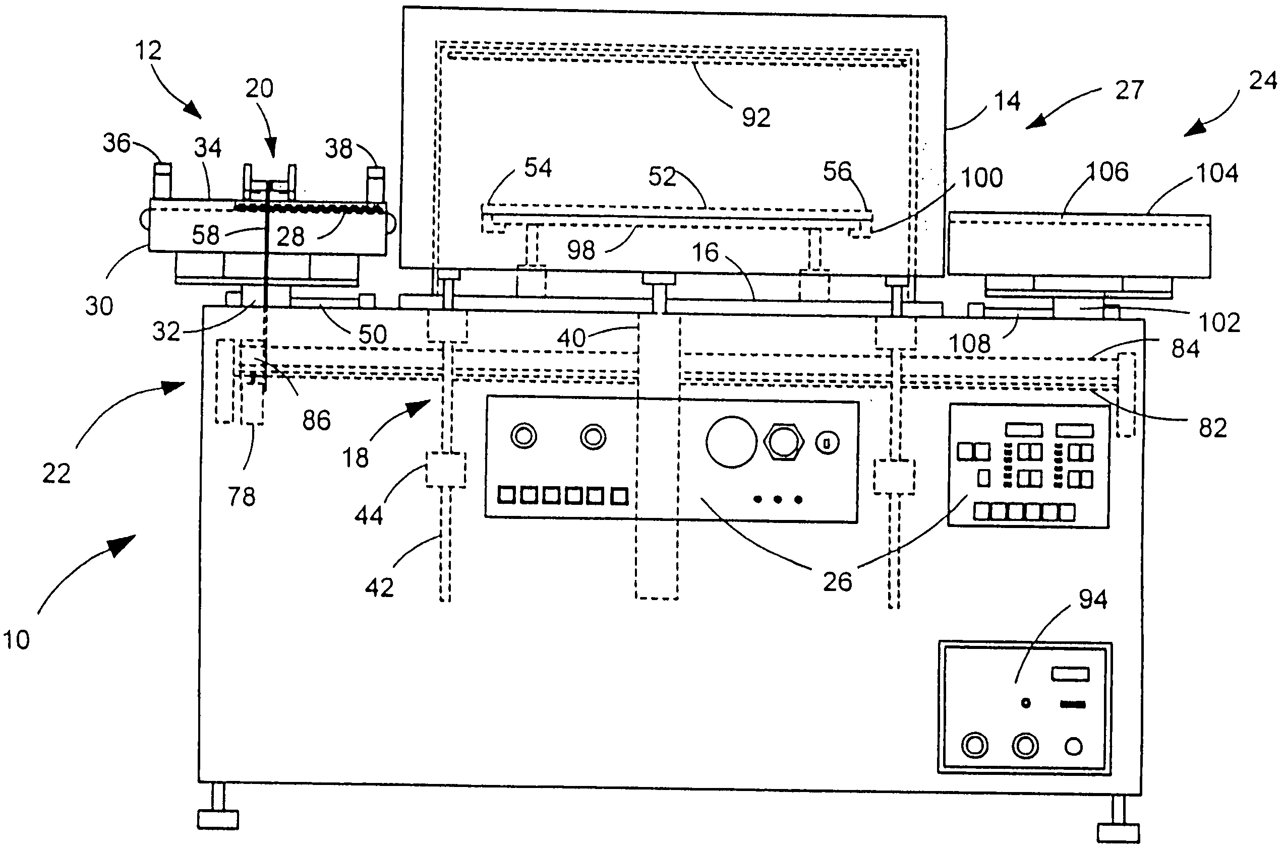
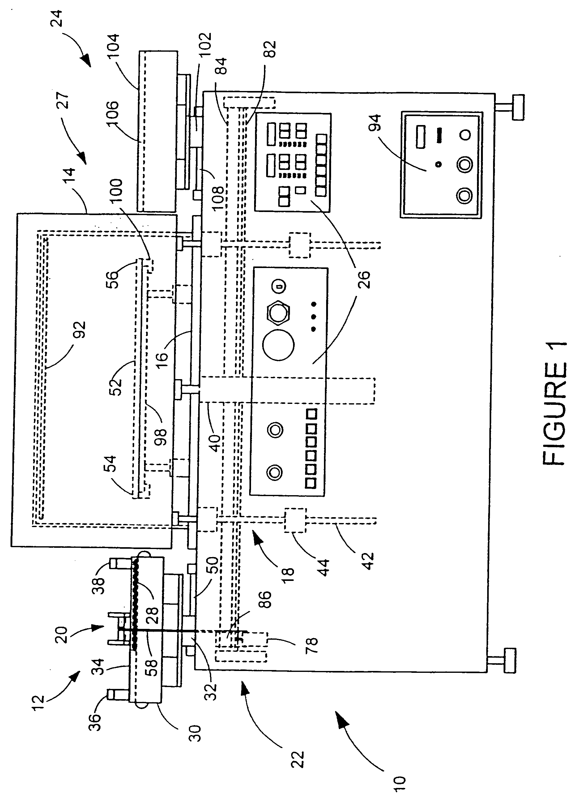
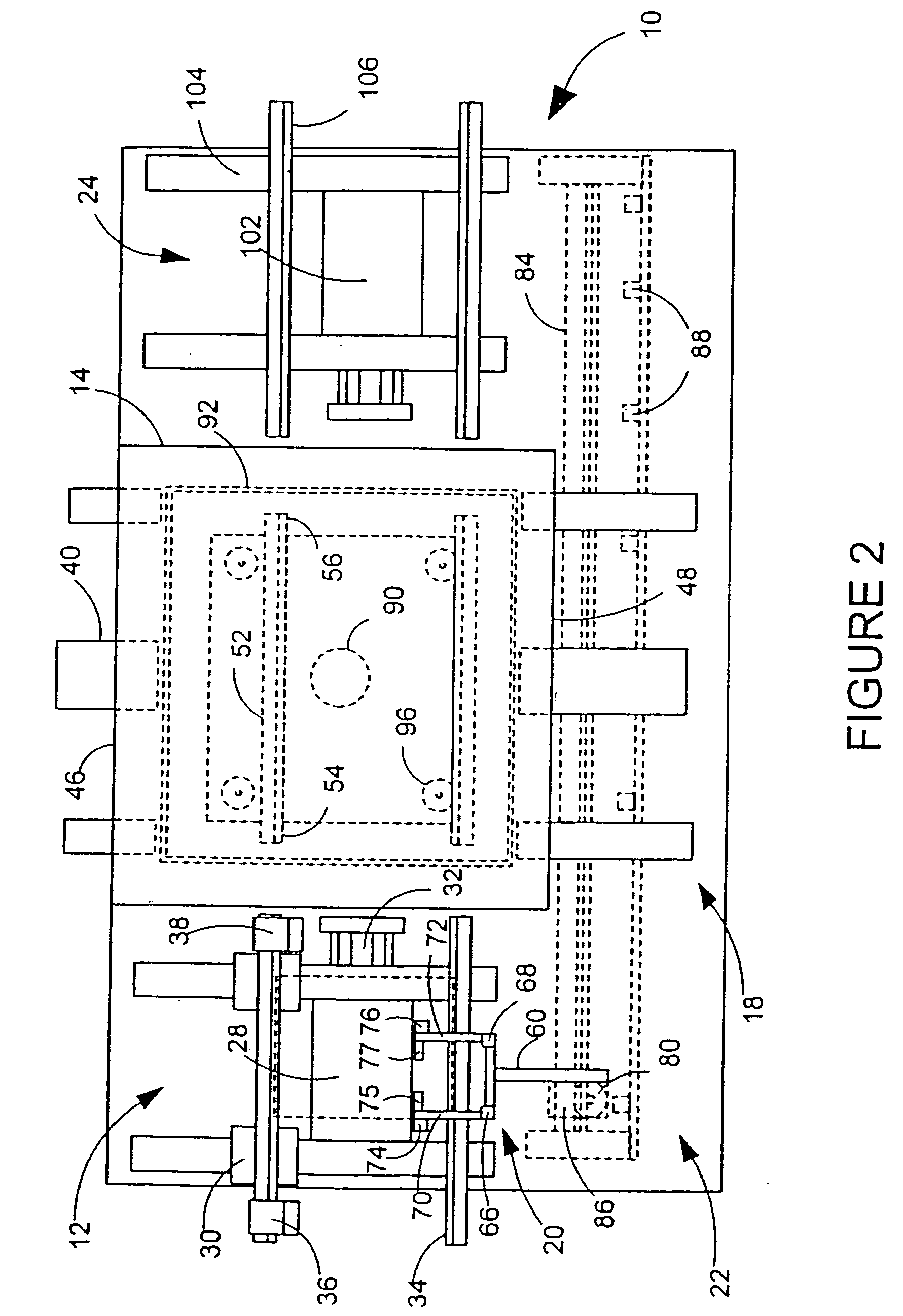
[0058] Referring to the front view of FIG. 1 of the drawings, the plasma treatment system 10 is shown to include the primary components of a conveyor input assembly 12, a reaction chamber 14 and chamber base 16, a chamber lifting assembly 18, a push mechanism 20 and associated linear drive assembly 22, an output assembly 24, an electronic control system 26, and a vacuum and plasma generating system 27. In the particular preferred embodiment 10 shown, printed circuit boards (PC boards) 28 are the electronic parts that are to undergo plasma reaction treatment, although it is to be understood that many other varieties of substrate objects may be substituted.
[0059] Referring now to both FIG. 1 and to the top plan view of FIG. 2, the conveyor input assembly 12 utilizes a number of different positioning and movement elements to assist in the transport of the PC boards 28 to the reaction chamber 14. Among these elements are a conveyor 30 and a conveyor position actuator 32, upon which the ...
embodiment 410
[0071] As shown in FIG. 8, the multi-level embodiment 410 incorporates a linear drive assembly 422 as before, but a push mechanism 420 now includes first and second catch assemblies 462 and 464 having first and second catch actuators 466 and 468 which are attached not only to first and second lower catch fingers 470 and 472 (not shown) but to first and second upper catch fingers 124 and 126 (see FIG. 7) as well. The lengths of the catch fingers (470, 472, 124, and 126) are again such as to extend over the travel areas of the PC boards 28. In operation, and referring now to FIGS. 6 and 9a, and also to the end view of FIG. 10, a first catch sensor 475 present on the push mechanism 420 locates the PC board 28 as before. The first catch actuator 466 then lowers the first lower catch finger 470 such that a first catch block 474 may abut and push the PC board 28 when the linear drive assembly 422 is activated. The push mechanism 420 moves the PC board 28 onto the upper input guide rails 1...
third embodiment
[0084] If used in a batch-processing manner, the magazines can be used with a variety of reaction chamber configurations, which have been fitted with vertical electrodes and DC biasing circuitry, as previously described. FIG. 13 shows a plasma treatment system 610, which can be used in manual batch-processing manner or used with robotic manipulation. A plasma treatment system 610 is shown, having an enclosure 612 surrounding a reaction chamber 614. A ground shelf 520 and a powered shelf 510 are shown having attached vertical electrodes 598. Magazines 620 filled with parts to be treated are shown seated on an adjustable shelf 622. The sides (not shown) of the magazines are either open or have slots fashioned to allow plasma flow to reach the parts. A DC bias applied to the powered and ground shelves serves to direct plasma flow through the magazine side slots or open sides to allow uniform treatment, in the manner previously described. The DC and RF power is input to the powered shel...
PUM
 Abstract
Description
Claims
Application Information
 - R&D
- Intellectual Property
- Life Sciences
- Materials
- Tech Scout
- Unparalleled Data Quality
- Higher Quality Content
- 60% Fewer Hallucinations
Browse by: Latest US Patents, China's latest patents, Technical Efficacy Thesaurus, Application Domain, Technology Topic, Popular Technical Reports.
© 2025 PatSnap. All rights reserved.Legal|Privacy policy|Modern Slavery Act Transparency Statement|Sitemap|About US| Contact US: help@patsnap.com


