
Fuel cell system, and operation and program for same

a fuel cell and electric technology, applied in the field of electric fuel systems, can solve the problems of difficult to diagnose potential problems, difficult to judge whether the voltage decline of a fuel cell is caused, and difficult to do, so as to facilitate detection and analysis of voltages, increase the volume of air bleed, and easy to take appropriate action.

Inactive Publication Date: 2005-03-03
PANASONIC CORP
View PDF20 Cites 76 Cited by
  • Summary
  • Abstract
  • Description
  • Claims
  • Application Information

AI Technical Summary

Benefits of technology

[0013] An advantage of the present invention is a fuel cell and process that facilitates detection and analysis of voltages and other cell parameters and the ability to readily take appropriate action when abnormal levels of electricity is generated from the cell.

Problems solved by technology

However, it is often difficult to diagnose potential problems from simply monitoring the voltage.
In particular, it is very difficult to judge whether the decline in voltage of a fuel cell is caused by an increase in the gas diffusion resistance as, for example, by the result of some obstruction that places limits on the amount of gas diffusion, or by an increase in reaction resistance as, for example, by the result of a declining level of reactivity of the electrolyte poles.
However, it is difficult to do so with the above mentioned conventional fuel cell system 1 because inverter 6 is connected to stacks 21, 22, etc., 2n in parallel.
However, the number of impedance measurement devices required to measure each fuel cell would be too high, and it would only increases the cost for the system.
As a result, there have been no highly reliable methods to find the causes of an abnormal operating fuel cell system, particularly with regard to the amount of electricity generated in fuel cells.

Method used


Image

  • Fuel cell system, and operation and program for same
  • Fuel cell system, and operation and program for same
  • Fuel cell system, and operation and program for same

Examples


example 1

[0174] The makings of the fuel cell electricity generating system in the Example 1:

[0175] First, a gas diffusion layer was created as follows: Immerse about 10 weight % of diffusive solution of Polytetrafluoroetheylene (Daikin Kogyou Lubron LDW-40) as dry weight on a carbon paper (Toure TGPH-060). Then, use a hot-air dryer to heat the paper to about 350° C. to dry the paper. Then, high ion molecule conductive layer was created from carbon powder and fluoride resin. In particular, prepare a dispersion liquid which is created from Denkablack of Denki Kagaku Kogyou as carbon powder with about 30 weight % of Polytetrafluoroethylene dispersion liquid (Daikin Kogyou Rubron LDW-40) as dry weight as the fluorine resin. Then, paint the prepared dispersion liquid on the dried carbon paper as previously described, and create a gas diffusion layer including a conductive layer containing a polymer by drying the dispersion liquid at about 350° C. by a hot-air dryer.

[0176] Then, a membrane-elect...

example 2

[0182] Fuel cells were created similar to Example 1, which were used to produce a fuel cell electricity generating system by using the same steps as Example 1. The same operations were carried out and the controls used were the same as FIGS. 7 to 9. However, in this example, the step of decreasing Uf (S30) and the step of increasing step Uf (S32) in FIG. 9 were not carried out.

[0183]FIG. 23 shows the cell voltage changes at different times of examples 2 to 6, and the one for example 2 is indicated by cell voltage 161. Even after 5000 hours from initially operating the system, the cell voltage 161 held at more than 0.70V.

example 3

[0184] Fuel cells were created similar to Example 1, which were used to produce a fuel cell electricity generating system of the first embodiment by using the same steps as Example 1. The same operations were carried out and the controls used were the same as FIGS. 7 to 9. However, in this example, the step of increasing the amount of air bleed (S25) and the step of increasing the amount of air bleed (S34) were ignored.

[0185]FIG. 23 shows a line 162 as the changes of the cell voltage of Example 3 as time passed. Even after 4500 hours from initially operating the system, the cell voltage 162 held at more than 0.70V.


PUM

PropertyMeasurementUnit
frequencyaaaaaaaaaa
frequencyaaaaaaaaaa
current densityaaaaaaaaaa

Abstract

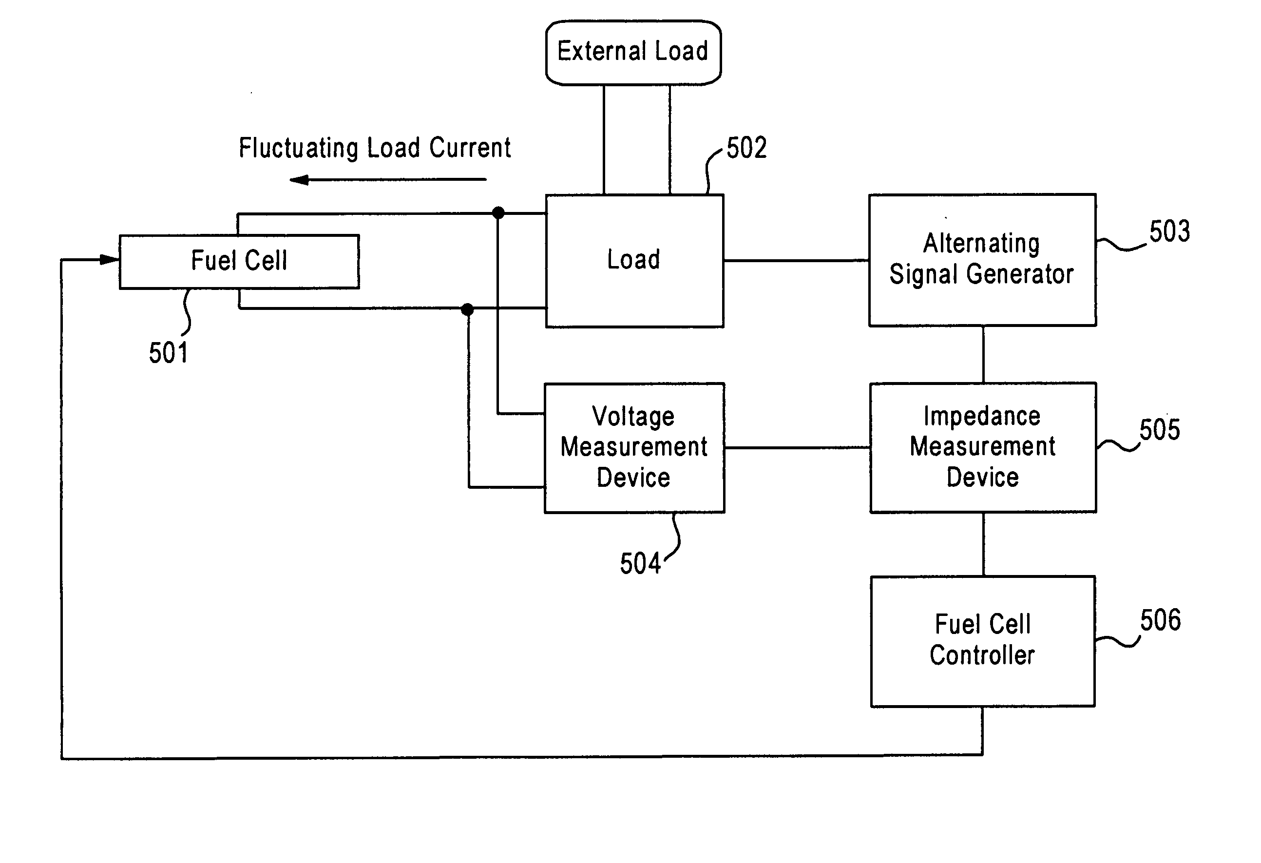
An electrolyte fuel system, its operation and program and a recording medium associated with the program is disclosed. Embodiments include a fuel cell system having a load electric current changing means for changing an amount of load electric current that runs in one ore more fuel cells which are operated to generate electricity, a measurement means for measuring voltage responses to the change in said load electric current, a calculating means for calculating impedance of said one or more fuel cells based on said voltage responses measured, and a fuel cell control means for controlling condition for operation of said one or more fuel cells by utilizing calculation results retrieved by said calculating means.

Description

FIELD OF THE INVENTION [0001] The present invention relates to an electrolyte fuel system, its operation and program and a recording medium associated with the program. The present invention is particularly applicable to detecting and reducing abnormal levels of electricity from being generated in a polymer electrolyte fuel system. BACKGROUND [0002] A fuel cell generates electricity by supplying an oxygen-based oxidizer to a cathode and supplying a hydrogen-based fuel gas to an anode. The fuel cell is either comprised of a cathode and an anode, or a stack of multiple fuel cells that are connected in series. During operation, the voltage of the fuel cell is generally monitored to determine whether an abnormal level of electricity is being generated to avoid damage to the cell and improve its efficiency. However, it is often difficult to diagnose potential problems from simply monitoring the voltage. [0003] In particular, it is very difficult to judge whether the decline in voltage of...

Claims


Application Information

Patent Timeline
Patent Type & Authority Applications(United States)
IPC IPC(8): G01R31/36H01M8/00H01M8/04
CPCG01R31/3651G01R31/3662H01M8/04223Y02E60/50H01M8/04298H01M8/04305H01M8/04231G01R31/367G01R31/389H01M8/04303H01M8/04228H01M8/04H01M8/04225
Inventor TAKEBE, YASUOTERANISHI, MASATOSHINAKAGAWA, TAKASHIUCHIDA, MAKOTOSEGAWA, TERUTSUGU
Owner PANASONIC CORP
Learn More