Method for manufacturing magnetic metal powder, and magnetic metal powder

a technology of magnetic metal powder and magnetic metal powder, which is applied in the field of magnetic metal powder, can solve the problems of inability to obtain metal powder that uses starting materials requiring strong reduction, inability to achieve strong reduction, and inability to use starting materials, etc., and achieve excellent magnetic characteristics

Inactive Publication Date: 2005-03-17
TDK CORPARATION
View PDF9 Cites 18 Cited by
  • Summary
  • Abstract
  • Description
  • Claims
  • Application Information

AI Technical Summary

Benefits of technology

[0027] The powder obtained by the process of the present invention is a single crystal powder composed of Fe as a main ingredient. The powder obtained by the process of the present invention is novel magnetic metal material in a spherical form with a mean particle size ranging from about 0.1 to 20 μm, which was unobtainable under conventiona

Problems solved by technology

The spray pyrolysis method uses liquid solutions as raw material, and consumes thermal energy for pyrolyzing water unrelated to the target metal sought during the high temperature processing step.
The moisture in the water vapor

Method used


Image

  • Method for manufacturing magnetic metal powder, and magnetic metal powder
  • Method for manufacturing magnetic metal powder, and magnetic metal powder
  • Method for manufacturing magnetic metal powder, and magnetic metal powder

Examples


embodiment examples

[0078] The present invention is explained with specific embodiment examples below.

embodiment example 1

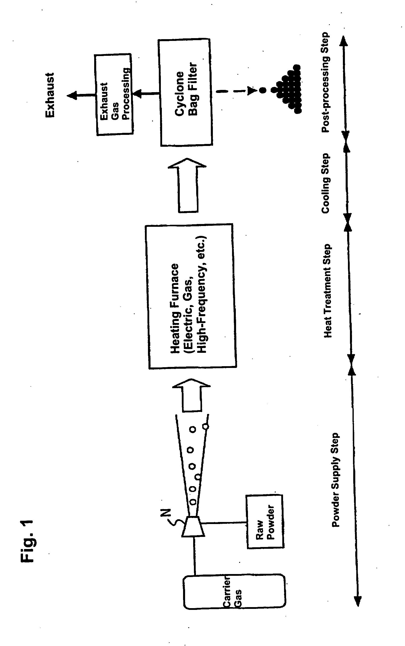
[0079] Raw powder, an iron oxide (Fe2O3) powder with a mean particle size of 3 μm, was fed to the heating furnace using as carrier gas a mixture of 68% hydrogen+nitrogen which acts as the reducing gas. The degree of purity of the iron oxide (Fe2O3) powder is 99.9%. The flow volume of carrier gas was 3 liters / minute. The temperature inside the furnace (heat treatment temperature) was 1,650° C. Moreover, the melting point of the iron oxide (Fe2O3) is 1,550° C. and the melting point of Fe is 1,536° C.

[0080] The powder thus obtained was observed with a scanning electron microscope (SEM). The results are shown in FIG. 8, and it was verified that the powder was in spherical form. Also, when the particle size of the powder was measured by a particle size distribution measurement instrument (LA-920 manufactured by Horiba Seisakusho), it was verified that the particle size distribution was from 0.5 μm to 6 μm, and the mean particle size was 2.2 μm.

[0081] The powder was subjected to X-ray d...

embodiment example 2

[0083] Raw powder, an iron oxide (Fe2O3, purity 99.7%) powder with a mean particle size of 0.2 μm, was fed to the heating furnace using as carrier gas a mixture of 4% hydrogen +Ar which acts as the reducing gas. The flow volume of carrier gas was 2 liters / minute. The temperature inside the furnace (heat treatment temperature) was 1,600° C. The powder thus obtained was observed with a scanning electron microscope (SEM), and it was verified that the powder particles were in a spherical shape. Also, when the particle size of the powder was measured by a particle size distribution measurement instrument, it was verified that the particle size distribution was from about 0.1 μm to 1 μm. It is believed that the reason particles having a particle size as large as 1 μm were obtained from raw powder of 0.2 μm was because part of the raw powder was melted with the powder being cohered, and the melt solidifying during the cooling process.

[0084] The powder was subjected to X-ray diffraction, a...


PUM

PropertyMeasurementUnit
Particle sizeaaaaaaaaaa
Magnetismaaaaaaaaaa
Affinityaaaaaaaaaa

Abstract

A method for manufacturing magnetic metal powder is provided. In the method, a powdered magnetic metal oxide is supplied to a heat treatment furnace with a carrier gas composed of a reducing gas. The heat treatment furnace is maintained at temperatures above a reducing action starting temperature for the powdered magnetic metal oxide and above a melting point of the magnetic metal in the powder. The powdered magnetic metal oxide is subject to a reducing process, and then magnetic metal particles, the resultant reduced product, is melted to form a melt. The melt is re-crystallized in a succeeding cooling step, to obtain single crystal magnetic metal power in substantially spherical form.

Description

BACKGROUND OF THE INVENTION [0001] 1. Field of the Invention [0002] The present invention relates to magnetic metal powder and its manufacturing method. [0003] 2. Description of Related Art [0004] The manufacturing method of metal powder can be classified by its starting raw material. In other words, metal powder can be manufactured from its gaseous phase, liquid phase and solid phase. And, as a specific method for manufacturing metal powder from the gaseous phase, the known methods are a chemical vapor deposition (CVD) method, sputtering method and vacuum deposition method. As for methods of manufacturing metal powder from the liquid phase, the known methods are a co-precipitation method, gas or water atomization method, spray method and spray pyrolysis method. As for making metal powder from solid phase, there is a pulverizing method that uses a crusher to pulverize metal nuggets into particles of appropriate sizes or administering a prescribed process on the pulverized powder. [0...

Claims


Application Information

Patent Timeline
IPC IPC(8): B22F1/00B22F9/22H01F1/06H01F1/20
CPCH01F1/06H01F1/24H01F1/20B22F9/22
Inventor TAKAYA, MINORUAKACHI, YOSHIAKIKOBUKE, HISASHIUEMATSU, HIROYUKI
Owner TDK CORPARATION
Why Eureka
Try Eureka