Reduction Smith-Talbot interferometer prism for micropatterning

a technology of interferometer and prism, applied in the field of imaging systems, can solve the problems of reducing the efficiency of phase shifting structure, limiting the approach to image resolution above 250 nm pitch values, and reducing the tolerance of tolerance, so as to achieve image geometry of very high resolution and extend the resolution of the invention

Inactive Publication Date: 2005-03-17
SMITH BRUCE W
View PDF7 Cites 32 Cited by
  • Summary
  • Abstract
  • Description
  • Claims
  • Application Information

AI Technical Summary

Benefits of technology

pitch of the mask pattern. A major advantage of the invention is the ability to image very high resolution geometry without limitations of the photomask. Additionally, ...

Problems solved by technology

In conventional phase-mask technique alignment, tolerances can be demanding due to the presence of diffraction orders other than +/−1.
The limited availability of phase masks with gratings pitch values less than 500 nm, and the quality of such masks near 500 nm, limits these approaches to image resolution a...

Method used


Image

  • Reduction Smith-Talbot interferometer prism for micropatterning
  • Reduction Smith-Talbot interferometer prism for micropatterning
  • Reduction Smith-Talbot interferometer prism for micropatterning

Examples


first embodiment

of the Invention

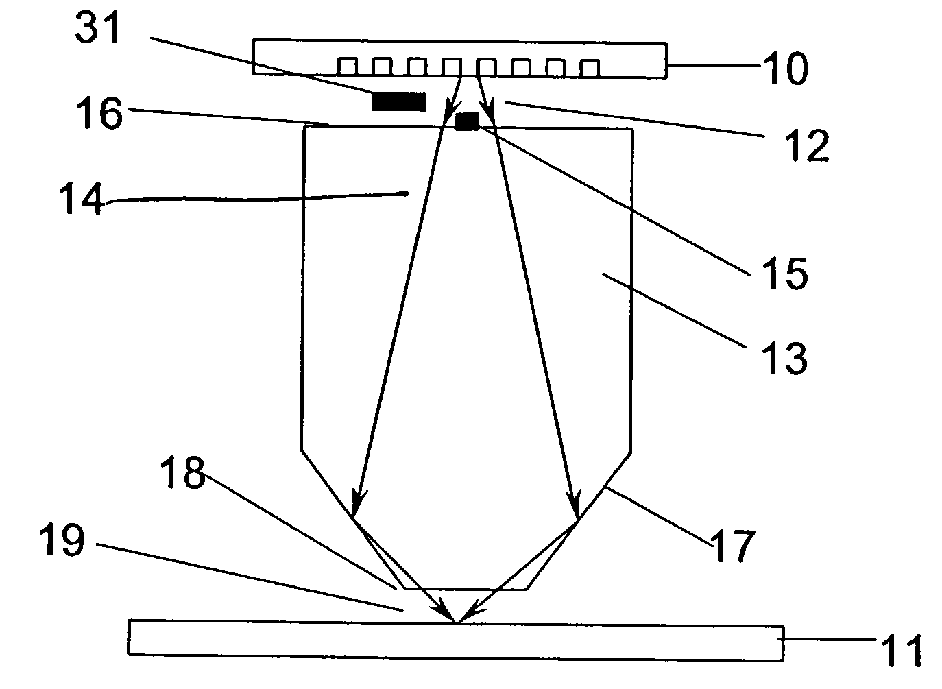
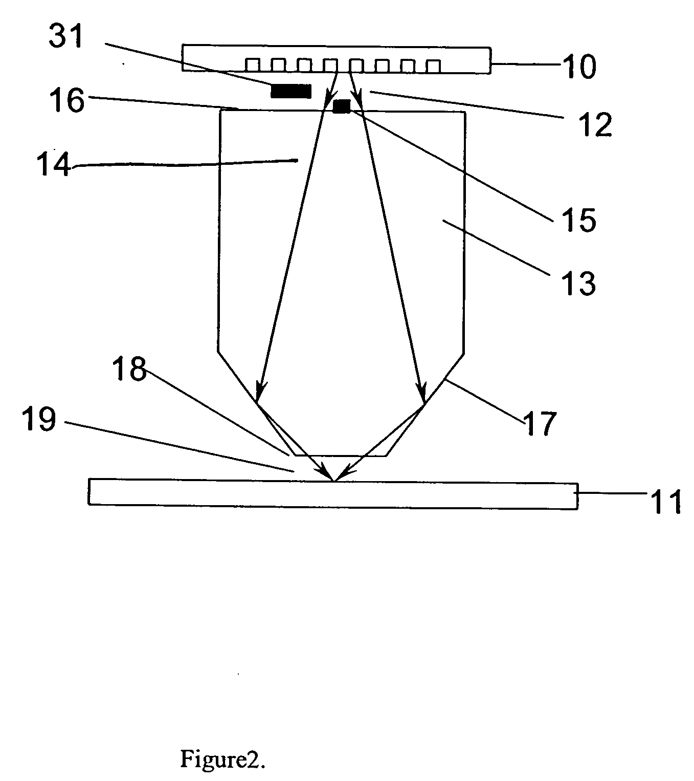
With reference to FIG. 2, the first embodiment of the invention is the simplest form. This example, however, does not limit the invention in any way. A grating photomask (10) is illuminated with radiation of wavelength (lambda) in the ultraviolet (UV) or visible spectrum, corresponding to the sensitivity requirement of the sensitized substrate at the imaging plane (11). The photomask is comprised of a metallic film deposited and patterned onto a glass substrate. The irradiation of the photomask (10) results in a diffraction pattern (12), where diffraction order beams are directed symmetrically toward a prism lens (13). The central diffraction order beam (14) is blocked by an obscuration (15), which can be a small metal plate placed between the photomask and the prism lens. Alternatively, the photomask (10) is a phase grating mask, comprised of a grating patterned directly into a glass substrate with patterns etched to a depth of lambda / [2(n−1)], where the central di...

second embodiment

of the Invention

A second embodiment of the invention is shown in FIG. 3. This embodiment is the four facet Smith-Talbot prism lens. This embodiment allows for either one or two pairs of diffraction order recombination. The radiation path from the diffraction order beams is directed toward four reflective facets (21) of the four facet prism lens (22), which are coated on the outermost surface with a reflective thin film coating, such as aluminum, chromium, or amorphous silicon, to act as mirror surfaces. The four facets (21) of the present embodiment allow for the creation of sinusoidal intensity patterns in orthogonal directions, either independently in separate imaging steps or together in one imaging step. By changing the orientation of the photomask by an angle of 90 degrees, the path of radiation from the resulting diffraction orders is directed from one parallel set of mirrored facets to the second orthogonal set. This allows for imaging of either horizontal (X) or vertical (Y...

third embodiment

Another way in which the present invention can exist is as a four facet prism lens, where the two pairs of orthogonal facets not at identical angles. The significant benefit of this embodiment is the ability to produce two different pitch values with a single prism lens. With reference to FIG. 6, a lens (31) is used between the photomask (32) and the Smith-Talbot prism lens (33) to collimate the diffraction order beams from the photomask so that they are normal to the first surface (34) of the prism lens. FIG. 5a is one orientation (A) of the prism lens and FIG. 5b is the other orientation (B). Beams that pass through the lens and are reflected off of facets in orientation A are interfered to produce a pitch:

P=lambda / (2×n′×sin(thetaA))

where sin(theta) is the interfering beam angle resulting from the facet angle in the prism. Beams that pass through the lens and are reflected off of facets in orientation B are interfered to produce a pitch:

P=lambda / (2×n′×sin(thetaB)).

By rotating t...


PUM


Abstract

Reduction Talbot interference imaging is carried out using a glass or fused silica prism, where at least two surfaces within the prism allow for an increase in the propagating ray angles at the image plane compared to the object (the photomask) plane. Furthermore, by adding a second orthogonal pair of surfaces, X and Y order recombination is made possible thus allowing for the imaging in an orthogonal direction with a two-order interference scheme as well as repeating checkerboard (island and hole) patterns with a four-order interference scheme. A benefit of the invention is the reduced requirements of the photo mask, allowing for diffraction limited imaging with UV wavelengths in a media with index of unity (air) or larger (an immersion fluid). The prism interferometer is known as a Smith-Talbot prism lens.

Description

FIELD OF INVENTION The invention relates to the imaging systems used in a variety of applications, including microlithography, photo-ablation, fabrication of Bragg gratings, ultraviolet (UV) inspection, and mastering of optical data storage media. BACKGROUND OF THE INVENTION Prior art systems for high resolution imaging applications utilize an illumination system, an object (a photomask), an objective lens, and an image plane. When an application is limited to the generation of repetitive patterns, interferometric approaches can be substituted and the system components can be limited to an illumination system, a phase object, a method of recombination, and an image plane. Common approaches for printing such patterns are interferometric methods and phase-mask methods. In the former technique, a single laser beam is split into two components, which are subsequently recombined at the image plane to produce an interference pattern. In the latter, a phase mask is used to diffract a las...

Claims


Application Information

Patent Timeline
IPC IPC(8): G03B27/52G03F7/20G06T
CPCG03F7/70233G03F7/70408G03F7/70341
Inventor SMITH, BRUCE W.
Owner SMITH BRUCE W
Why Eureka
Try Eureka