

Method of reducing sulfur in hydrocarbon feedstock using a membrane separation zone
a technology of hydrocarbon feedstock and separation zone, which is applied in the field of reducing sulfur content in sulfur-containing hydrocarbon feedstock, can solve the problems of increasing cost and difficulty, increasing refinery operating costs, and reducing the permissible level of sulfur in hydrocarbon fuels, so as to reduce the sulfur content of sulfur-containing hydrocarbon feedstock, the boiling point is reduced, and the effect of sufficient flux and selectivity
- Summary
- Abstract
- Description
- Claims
- Application Information
AI Technical Summary
Benefits of technology
Problems solved by technology
Method used
Image

Examples
example 1
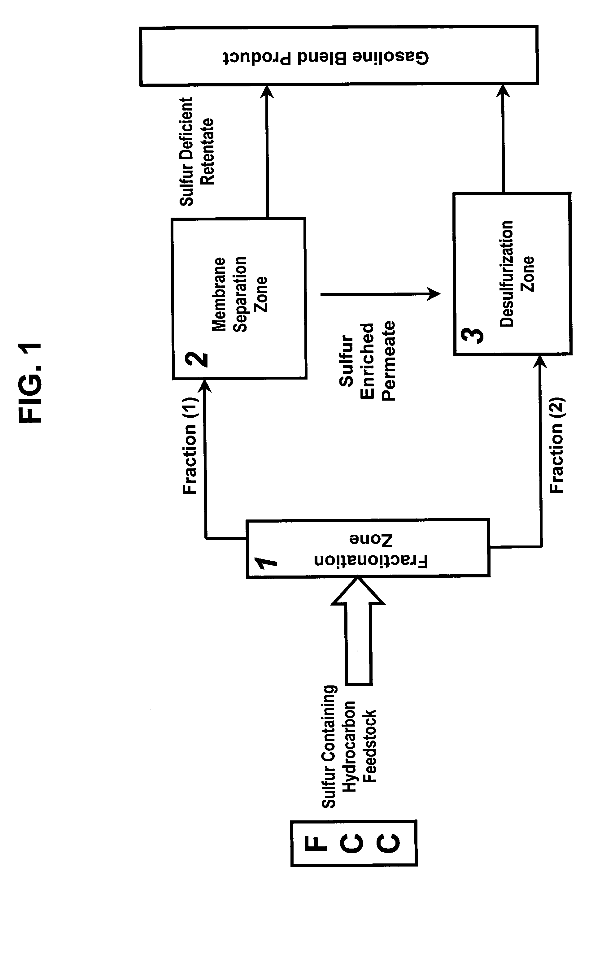
Fraction (1)
[0073] An overhead from a CDHydro Unit having a final boiling point of in the range of 100-300° F. was obtained for further separation through a Membrane Separation Zone according to the invention. The content of the overhead had the composition indicated in the Table below.
CD HydroCompositionOverheadppm SMercaptans11.1Thiophene96.2Methyl Thiophenes19.5Tetrahydro Thiophene2.0C2-Thiophenes0.0Thiophenol0.0C3-Thiophenes0.0Methyl Thiophenol0.0C4-Thiophenes0.0Unidentified Sulfur Species0.0Benzo Thiophene0.0AlkylBenzo Thiophene0.0Total128.8
example 2
Membrane
[0074] A polyurea-urethane membrane is prepared as follows.
[0075] A polyurea / urethane (PUU) composite membrane is formed through coating of a porous substrate following the methods of U.S. Pat. No. 4,921,611. To a solution of 0.7866 g of toluene diisocyanate terminated polyethylene adipate (Aldrich Chemical Company, Milwaukee, Wis.; Cat. #43, 351-9) in 9.09 g of p-dioxane is added 0.1183 g of 4-4′-methylene dianiline (Aldrich; #13,245-4) dissolved in 3.00 g p-dioxane. When the solution began to gel it is coated with a blade gap set 3.6 mil above a 0.2 micron pore size microporous polytetrafluoroethylene (PTFE) membrane (W. L. Gore, Elkton, Md.). The solvent evaporates to give a continuous film. The composite membrane is then heated in an oven 100° C. for one hour. The final composite membrane structure has a PUU coating 3 microns thick measured by scanning electron microscopy. The membrane shows an enrichment factor of 7.53 for thiophen and 3.15 for mercaptans.
[0076] The ...
example 3
Membrane Separation Zone
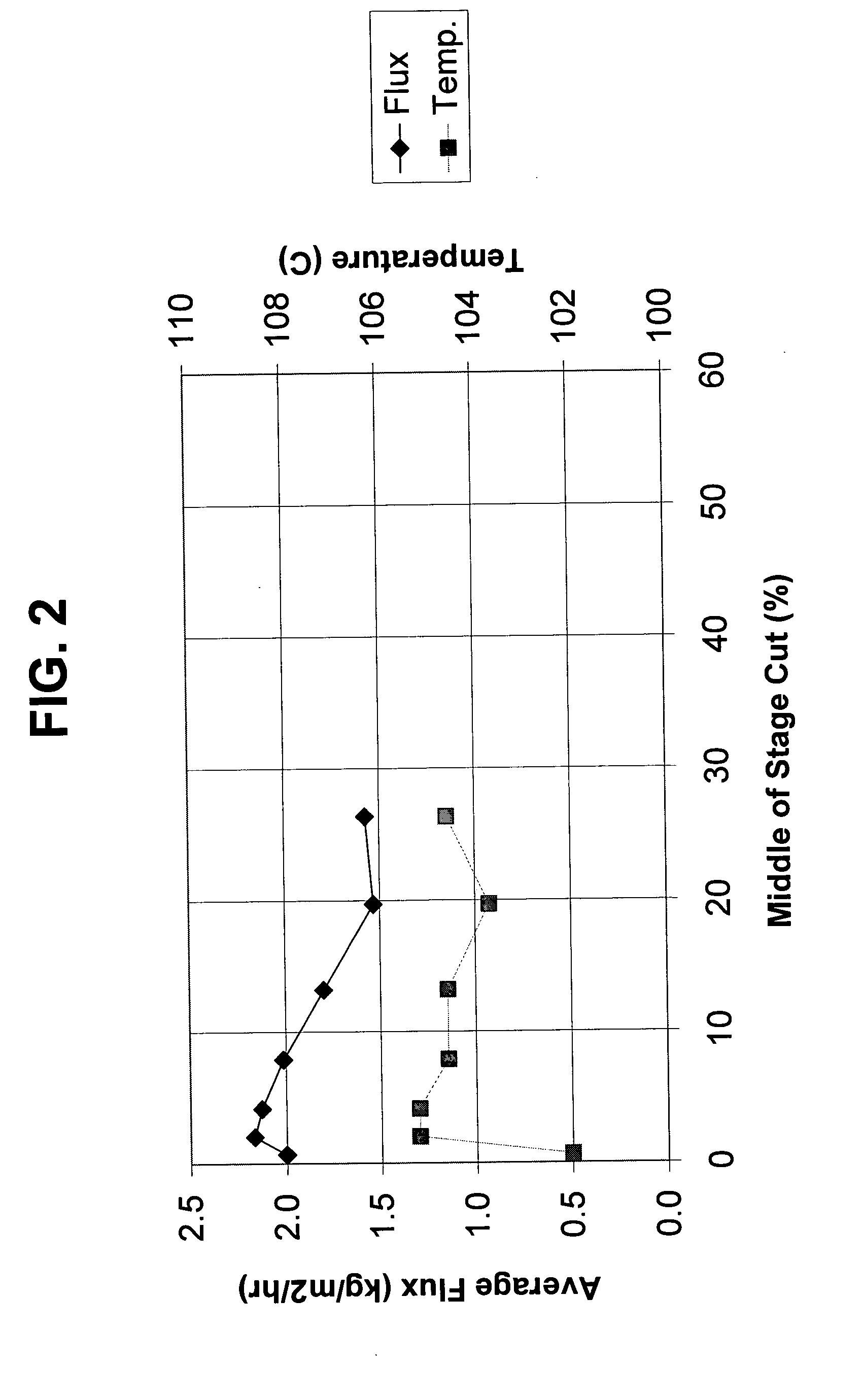
[0077] The overhead from Example 1 was pumped into a Membrane Separation Zone containing a membrane prepared according to Example 2. The separation was conducted under pervaporation conditions. Specifically, the overhead was pumped at an average flux (kilograms per square meter per hour) and temperature (C.°) illustrated in FIG. 2.
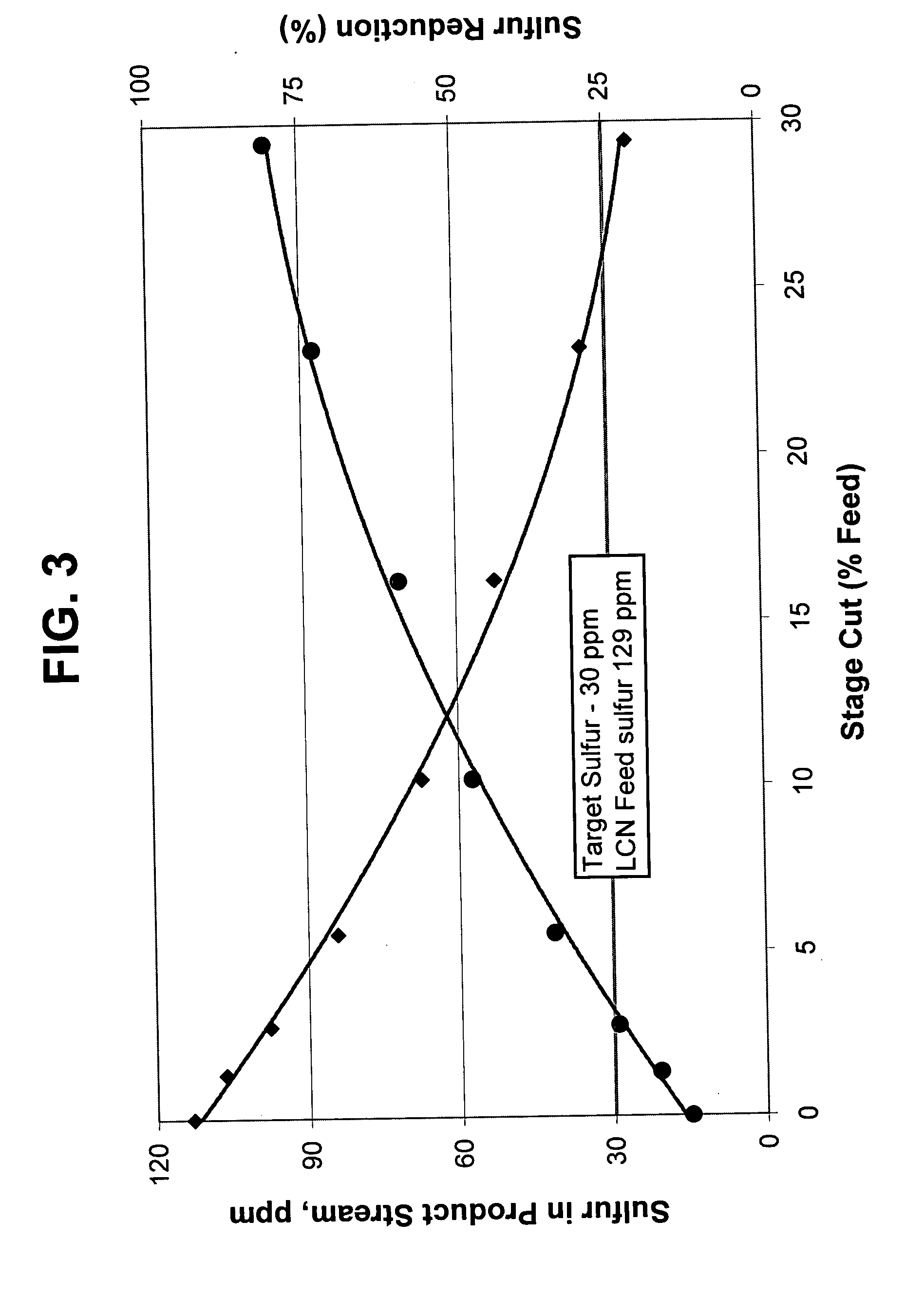
[0078]FIG. 3 shows the sulfur content in parts per million (ppm) in the membrane retentate as permeate is collected in amounts based on overhead content. This data is plotted with (♦). FIG. 3 also shows the percentage of sulfur reduction at each plot of sulfur content. Briefly, this graph shows that over 75% sulfur reduction and levels of less than 25 ppm sulfur can be obtained while maintaining at least 70% of the original overhead, thereby leaving 30% of the overhead that has to be routed to the sulfur reduction zone of the invention.
[0079]FIG. 4 shows that the olefin distribution of the overhead feed is significantly maintaine...
PUM
 Abstract
Description
Claims
Application Information