Preparation of soft magnetic thin film

a soft magnetic and thin film technology, applied in the field of soft magnetic thin film preparation, can solve the problems of non-metallic components, detracting from the saturation flux density of the cofe alloy film obtained by this method, and a less satisfactory saturation flux density, so as to achieve high saturation flux density, and low coercivity

Inactive Publication Date: 2005-04-21
OSAKA TETABUYA
View PDF15 Cites 2 Cited by
  • Summary
  • Abstract
  • Description
  • Claims
  • Application Information

AI Technical Summary

Benefits of technology

[0018] According to the invention, a soft magnetic thin film of a cobalt and iron-based alloy can be prepared without a substantial drop of saturation flux density from its theory. That is, a soft magnetic thin film having a high saturation flux density can be prepared in an efficient manner. Heat treatment of the film following deposition converts the film into a desired soft magnetic thin film having a high saturation flux density and even a low coercivity at the same time.

Problems solved by technology

The CoFe alloy film obtained by this method, however, has a less satisfactory saturation flux density.
With this method, however, non-metallic components such as boron originating from the reducing agent are incorporated in the CoFe alloy film in addition to Co and Fe, detracting from its saturation flux density.

Method used


Image

  • Preparation of soft magnetic thin film
  • Preparation of soft magnetic thin film
  • Preparation of soft magnetic thin film

Examples


reference example 1

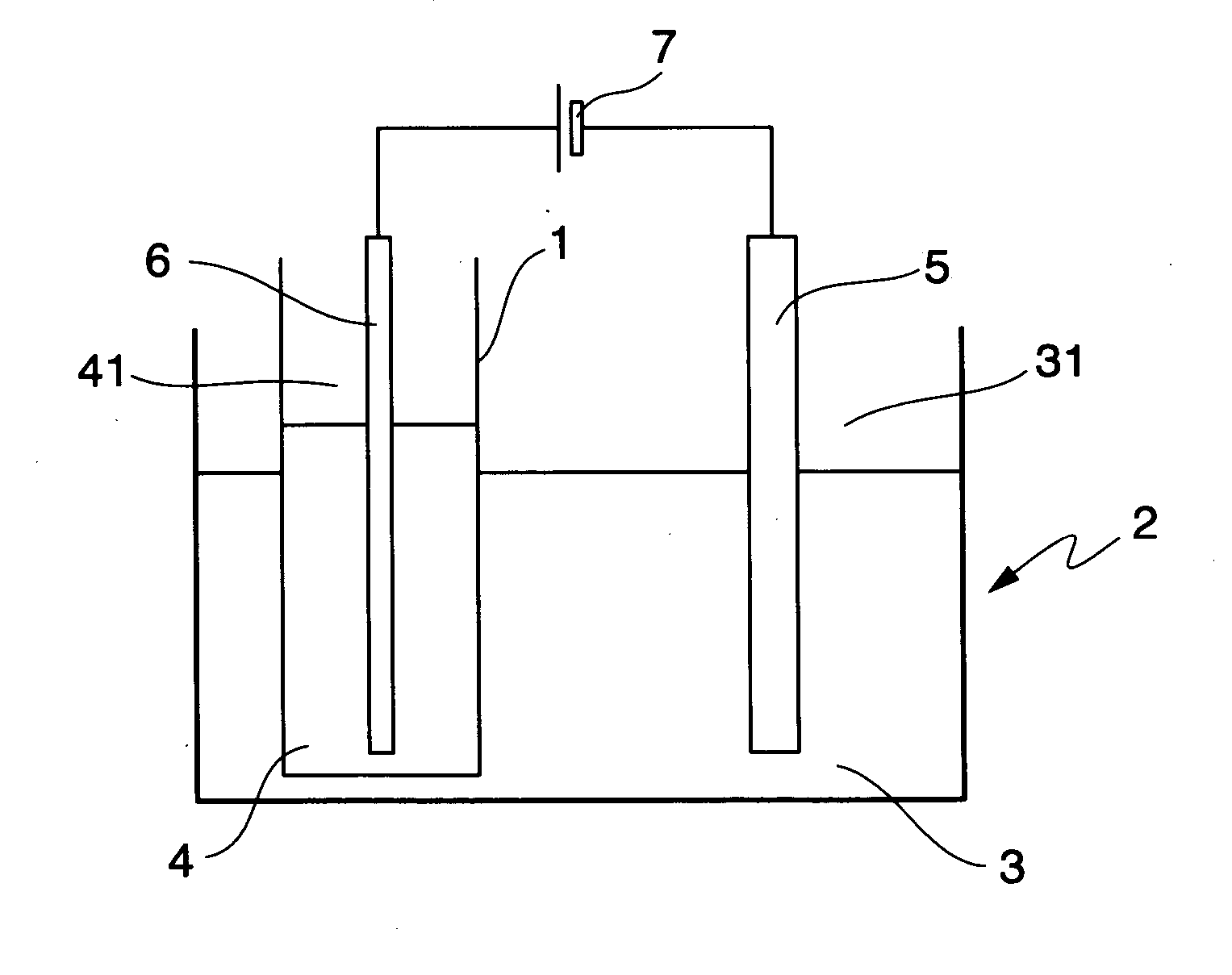
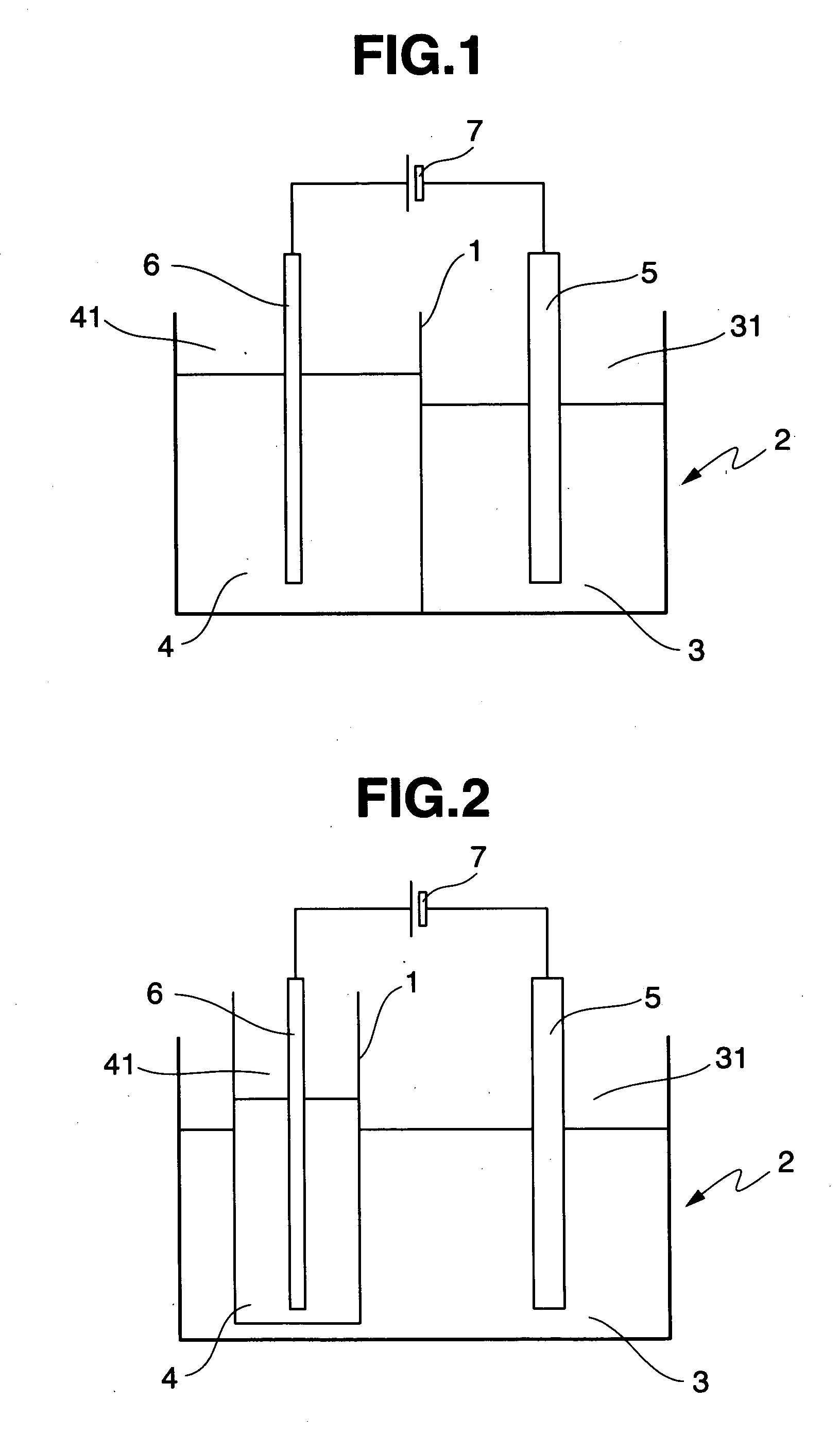
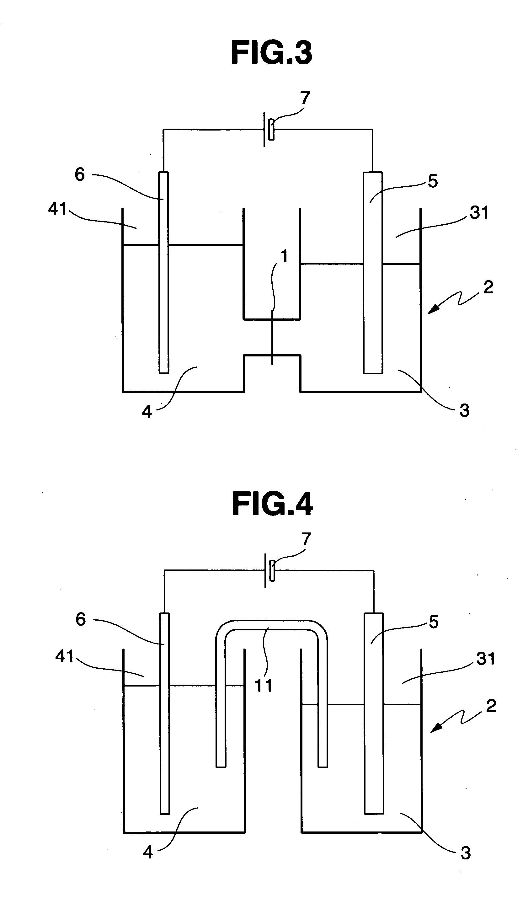
[0051] Using a plating system as shown in FIG. 4, a soft magnetic thin film (1 μm) of CoFe alloy was deposited on a substrate by electroplating using a plating solution under plating conditions as shown below. There were used an anode of platinum, a salt bridge of an aqueous saturated potassium chloride solution gelled with agar, and an electrolyte solution in the form of an aqueous 10 vol % sulfuric acid.

Plating solutionCobalt sulfate0.055-0.06mol / dm3Iron(II) sulfate0.04-0.045mol / dm3Boric acid0.4mol / dm3Ammonium chloride0.4mol / dm3Sodium dodecylsulfate0.01g / dm3pH 2.3Plating conditionsPlating solution temperature18° C.Cathode current density20mA / cm2RDE agitation1,000rpm

[0052] The magnetic property (saturation flux density Bs) of the soft magnetic thin film thus obtained was measured by a vibrating sample magnetometer (VSM), and the composition thereof was analyzed by x-ray fluorescence (XRF) and inductively coupled plasma (ICP) emission spectrometry. The results are shown in Table 1...

reference example 2

[0053] A soft magnetic thin film (1 μm) was deposited as in Reference Example 1 except that the plating solution of Reference Example 1 was modified to contain 0.05-0.055 mol / dm3 of cobalt sulfate and 0.045-0.05 mol / dm3 of iron(II) sulfate. The magnetic property and composition of the soft magnetic thin film thus obtained were examined, with the results shown in Table 1.

reference example 3

[0054] A soft magnetic thin film (1 μm) was deposited as in Reference Example 1 except that the plating solution of Reference Example 1 was modified to contain 0.045-0.05 mol / dm3 of cobalt sulfate and 0.05-0.055 mol / dm3 of iron(II) sulfate. The magnetic property and composition of the soft magnetic thin film thus obtained were examined, with the results shown in Table 1.


PUM

PropertyMeasurementUnit
temperatureaaaaaaaaaa
saturation flux densityaaaaaaaaaa

Abstract

A soft magnetic thin film of CoFe alloy having a high Br and low Hc is prepared by furnishing a plating tank including cathode and anode compartments which are separated by a diaphragm or salt bridge so as to permit charge transfer, but inhibit penetration of Fe ions, feeding a plating solution containing Co ions and divalent Fe ions to the cathode compartment, feeding an electrolyte solution to the anode compartment, immersing a substrate in the plating solution, immersing an anode in the electrolyte solution, electroplating, and heat treating the plated film at 100-550° C.; or by immersing a substrate and a soluble anode in a plating solution containing Co ions and divalent Fe ions, electroplating, and heat treating the plated film at 100-550° C.

Description

BACKGROUND OF THE INVENTION [0001] 1. Technical Field [0002] This invention relates to methods for preparing soft magnetic thin films based on cobalt and iron, and soft magnetic thin films obtained therefrom. [0003] 2. Background Art [0004] Soft magnetic thin films are currently on widespread use in electronic applications such as electronic parts including thin-film magnetic heads, thin-film inductors and thin-film transformers. In particular, in order for a thin-film magnetic head to perform high density magnetic recording, it is necessary to shrink recorded bits, which in turn, requires the thin-film magnetic head to produce a high strength magnetic field for writing. Then the soft magnetic thin film used in the thin-film magnetic head must be formed of a magnetically soft material having a high saturation flux density (Bs). With respect to thin-film inductors and thin-film transformers which are required to reduce their size and the thickness of film, a demand for a magnetically...

Claims


Application Information

Patent Timeline
Patent Type & Authority Applications(United States)
IPC IPC(8): C25D3/56C25D5/18C25D5/50C25D17/00
CPCC25D3/562C25D5/18C25D5/50C25D17/002C25D5/617
Inventor OSAKA, TETSUYAYOKOSHIMA, TOKIHIKO
Owner OSAKA TETABUYA
Why Eureka
Try Eureka