General radio frequency synthesizer (GRFS)

a radio frequency synthesizer and general technology, applied in the field of general radio frequency synthesizers, can solve the problems of complicated design of channel switching capabilities, and achieve the effect of compactness, cost-effectiveness and ease of fine tuning

a radio frequency synthesizer and general technology, applied in the field of general radio frequency synthesizers, can solve the problems of complicated design of channel switching capabilities, and achieve the effect of compactness, cost-effectiveness and ease of fine tuning

US20050090208A1Inactive Publication Date: 2005-04-28LIAO RICH

Image

  • General radio frequency synthesizer (GRFS)
  • General radio frequency synthesizer (GRFS)
  • General radio frequency synthesizer (GRFS)

Examples


Embodiment Construction

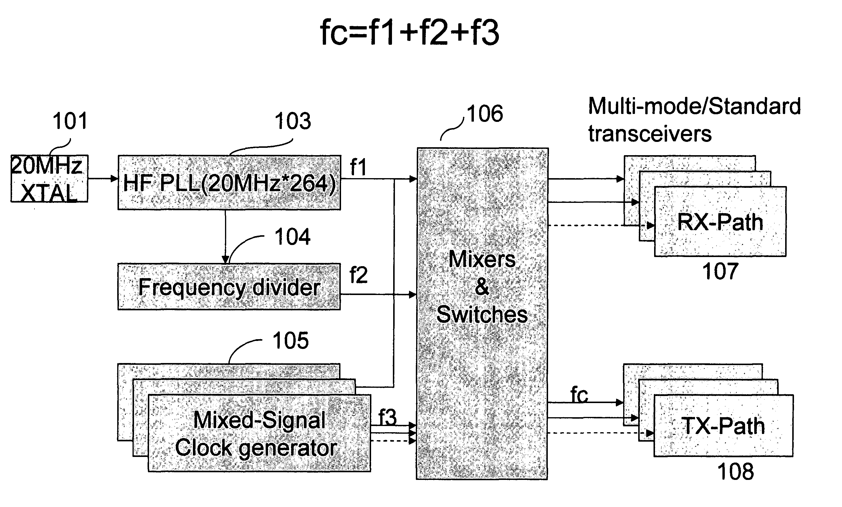
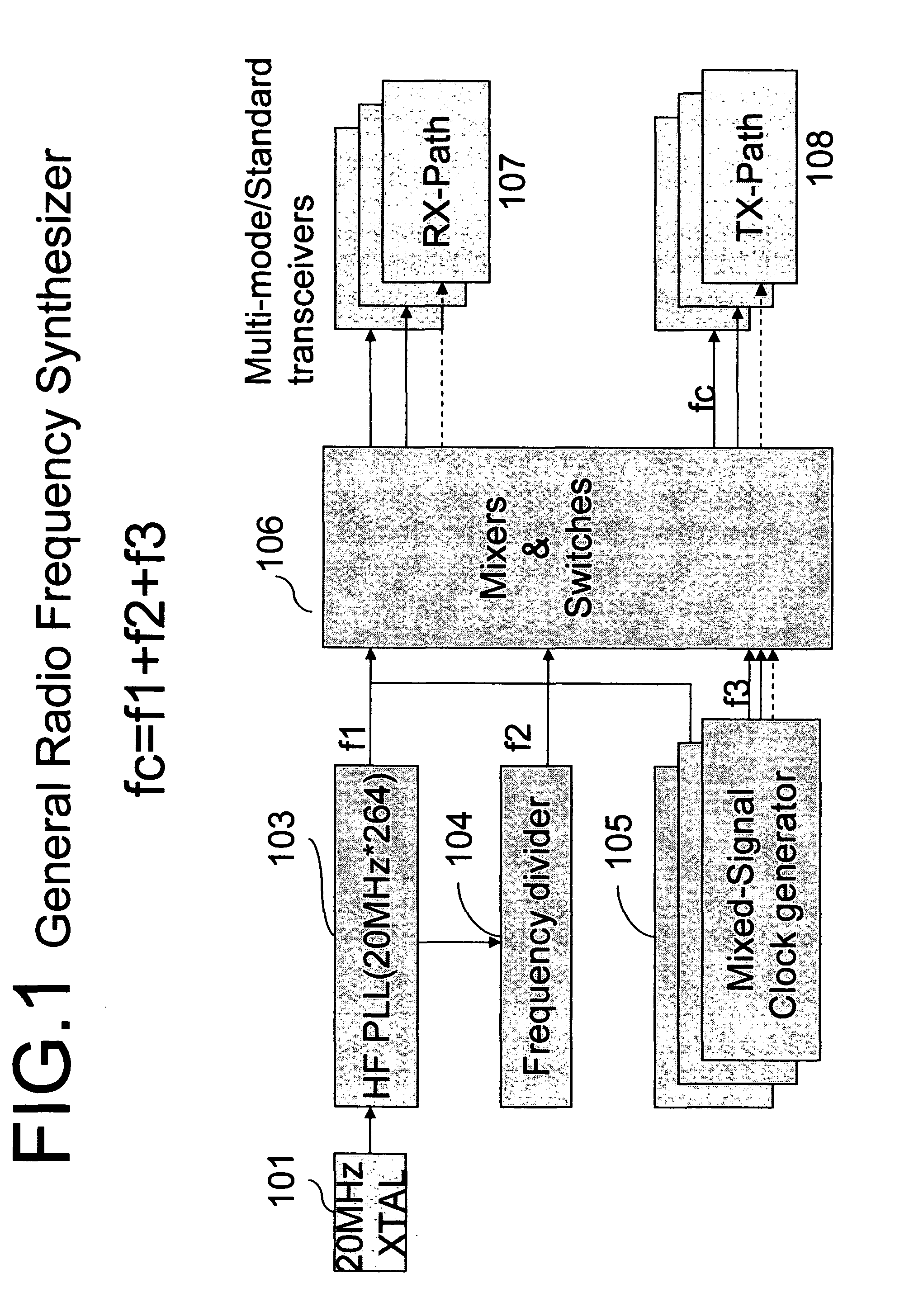
[0023] The present invention shown in FIG. 1 provides a synthesizer for use in multi-mode, multi-standard and multi-port communication devices, which, unlike conventional synthesizers, uses a PLL with a VCO to cause an output signal frequency to vary in dependence upon an input control voltage and programmable frequency dividers. The frequency synthesizer is composed of one single constant high radio frequency generator based on PLL and dividers as shown in FIG. 5 to generate two classes of frequencies f1 and f2 in FIG. 4 and a mixed-signal f3 frequency generator in FIG. 6 to provide instant and simultaneously channel switching lock capability. Those aspects of the present invention that differ from a conventional synthesizer will accordingly be described hereinafter, with the conventional PLL single frequency generator portions not being described in detail. Furthermore, the high frequency generator for f1 and f2 is not necessarily generated by traditional VCO circuits, it can use ...


PUM


Abstract

The present invention provides cost-effective synthesizer and transceiver architecture having an instant channel switching for multiple wireless / wire network communication standards such as IEEE802.11 ab / g, Bluetooth, WCDMA, GSM QuadBand, CDMA dualband, GPS. This invention also enables multiple communication standards or multiple channels in one standard share the same fundamental frequency generators. This allows for a method of operating the transceiver and synthesizer, methods and apparatus of establishing or reestablishing a instant or simultaneously channel switching lock condition in a communication standard or among different communication standards.

Description

FIELD OF THE ART [0001] The present invention relates to the field of signal processing and frequency synthesizer and communication transceiver architectures, more particularly, the present invention relates to a synthesizer, and in particular a synthesizer with PLL and a clock generator based on mixed-signal waveform generation for multi-channels, multi-mode, multiple wireless and wire communications standards in a class of very compact and cost-effective architectures. BACKGROUND DESCRIPTION OF THE RELATED ART [0002] A communication system transfers information between a source and a destination. Generally, a communication system includes at least one transmitter and one receiver which transmit and receive information signals over some media, respectively. This media may be cable wiring or no wiring, like atmosphere. When communications occur over no wiring, they are commonly referred to as ā€œwirelessā€ communications. Examples of wireless communications systems include wireless mod...

Claims


Application Information

Patent Timeline
28 Apr 2005
Publication
US20050090208A1
IPC
H04B1/40
CPC
H04B1/406; H03L7/18
Inventors
LIAO, RICH