Method and apparatus for plasma generation

a plasma flow and apparatus technology, applied in the field of methods and apparatus for generating plasma flows, can solve the problems of high anode-cathode potential drop, limited anode-cathode voltage drop during the starting period of the discharge, and limited anode-cathode voltage drop during the entire discharge time, so as to increase the driving current and prevent the transition. , the effect of high probability of arc discharg

Active Publication Date: 2005-05-05
CEMECON +1
View PDF18 Cites 80 Cited by
  • Summary
  • Abstract
  • Description
  • Claims
  • Application Information

AI Technical Summary

Benefits of technology

[0040] 6. The plasma can be produced in a magnetron magnetic configuration in which combined high intensity current non-quasi-stationary discharges and high intensity current quasi-stationary discharges in crossed fields are used.
[0041] The combinations of discharges in crossed electric and magnetic fields mentioned above made in a magnetron magnetic configuration allow the production of plasma flows of preferably gas or gas and metal or most preferably of a metal plasma flow. For quasi-stationary discharges the choice of method can be based on the different efficiencies of the low and high current intensity discharges for sputtering and ionization in the different cases.
[0042] The discharges in crossed fields have, as has been mentioned above, a natural tendency of forming spoke-shaped azimuthal plasma inhomogeneities—arc discharges. The probability of the transition of an EXB discharge in magnetron type devices to a contracted arc discharge increases with an increasing driving current. In low current discharges arcing occurs very rarely and it is possible to prevent the transition to arc discharges by specially adapted arc suppression schemes in the discharge power supply. In high current discharges there is a very high probability of arc discharges being formed and solutions to the problem of suppressing arc formation using similar schemes are not efficient. As will be described herein, arc suppression can be achieved using a now discovered phenomenon of dependence of arc formation on the plasma confinement properties of the magnetron magnetic configuration and on the time between discharges. The balanced magnetron magnetic configuration has relatively low plasma confinement properties. Therefore, for achieving efficient arc suppression, it is necessary to use a magnetic field having a high strength. In this case the plasma losses caused by diffusion will decrease as B−2 in the case of classic diffusion or as a B−1 in the case of Bohm diffusion, where B is the strength of the magnetic field. It was found that for a balanced magnetron magnetic configuration, in order to achieve efficient arc suppression, it is necessary to have a magnetic field strength of the radial B component of about 0.07-0.3 T, the radial direction here taken as directions parallel to the substantially flat surface of the cathode or target. Unbalanced and cusp-shaped magnetic configurations have improved plasma confinement properties; therefore, for effective arc suppression it is sufficient to have a magnetic field strength of about 0.04-0.3 T.
[0043] The plasma confinement properties of the magnetic configuration strongly affect the lower limit of the operating pressure used in the space at the cathode. It was found that for improving the plasma confinement properties the operating pressure of the EXB discharge should be decreased. For a certain operating frequency a gas atmosphere is required only for starting the discharge. After the starting period it is possible to initiate the discharge by the residual plasma density left from the previous pulse. In this case metal vapor is produced by using the selfsputtering phenomenon and the plasma in the magnetic trap contains primarily ions of the target metal. The plasma flow from the magnetic trap contains preferably ions of the target metal as well.
[0044] Generally, it can be said that the primary concept of the method described herein is to combine the magnetic configuration having improved plasma confinement properties with low and high intensity current quasi-stationary discharges and non-quasi-stationary discharges or DC and high intensity current discharges for generating stable and intensive plasma flows. Low and high intensity current quasi-stationary discharges and non-quasi-stationary discharges are produced one after another with a repeating frequency exceeding a minimal critical value depending on the plasma confinement properties of the magnetic trap. In the case of DC sputtering discharges, a high rate of ionization of gas and metal vapor is produced by a periodic repetition of the ionizing discharges.

Problems solved by technology

The electrical resistance of the anode-cathode gap is high resulting in a high anode-cathode potential drop.
For devices having a low sputtering rate and low plasma losses it results in an anode-cathode voltage drop limitation during the starting period of the discharge.
For devices having a high sputtering rate it results in an anode-cathode voltage drop limitation during all of the discharge time.
Thus, it can be said that it is impossible to generate, by a separate low intensity current quasi-stationary discharge, or by a separate high intensity current discharge in crossed fields, highly ionized metal plasma fluxes.
But, as will be shown hereinafter, if transient discharges are implemented in magnetron sputtering devices by either high intensity current discharges or by low intensity current discharges it is impossible to generate highly ionized intensive metal plasma fluxes.
The drawbacks of this method of metal plasma production include the complexity of the RF-ionization technique and the high pressure of the sputtering gas required for producing the low-density plasma.
The high pressure of the sputtering gas is required because of the high energy consumption necessary for producing a low-density plasma.

Method used


Image

  • Method and apparatus for plasma generation
  • Method and apparatus for plasma generation
  • Method and apparatus for plasma generation

Examples


second embodiment

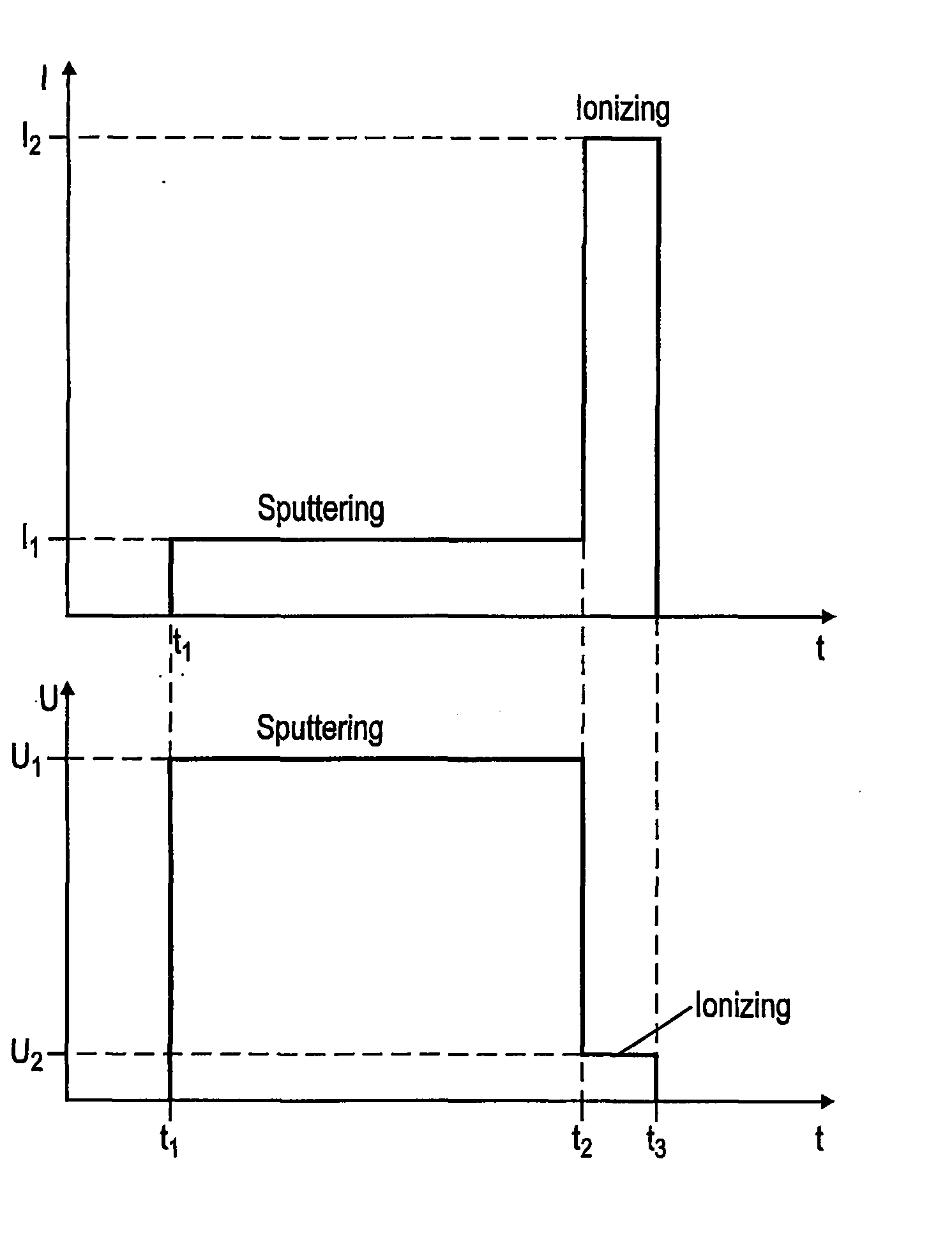
[0093]FIG. 5 is a diagram similar to that of FIG. 4 but here, the time intervals of the sputtering and ionizing discharges are separated by a short time interval of length A=(t3-t2) during which no voltage is applied.

third embodiment

[0094]FIGS. 6a, 6b are diagrams of the current as a function of time illustrating how the pulses can be applied according to a In the diagram of FIG. 6a a constant current IDC is shown used for achieving the sputtering discharge. This constant current is combined with a pulsed ionizing discharge as shown in FIG. 6b, the driving current I2 during the pulses of the ionizing discharges being considerably higher than the constant current. t3 is the start time of the intervals of the ionizing discharges beginning and t4 is the time when the ionizing discharges end. FIG. 7a is a diagram showing the conductivity δ and plasma density n as a function of time in the plasma confinement region. The driving current pulses are shown in the diagram of FIG. 7b as a function of time. The filling of the plasma confinement region by metal vapor can be produced by a DC discharge, see FIGS. 6a, 6b, or by pulsed low current discharges, as in FIGS. 3a, 3b, 4 and 5. In FIG. 7a δmax and nmax are the maxima...


PUM

PropertyMeasurementUnit
frequencyaaaaaaaaaa
peak voltagesaaaaaaaaaa
frequencyaaaaaaaaaa

Abstract

In a simple method and device for producing plasma flows of a metal and/or a gas electric discharges are periodically produced between the anode and a metal magnetron sputtering cathode in crossed electric and magnetic fields in a chamber having a low pressure of a gas. The discharges are produced so that each discharge comprises a first period with a low electrical current passing between the anode and cathode for producing a metal vapor by magnetron sputtering, and a second period with a high electrical current passing between the anode and cathode for producing an ionization of gas and the produced metal vapor. Instead of the first period a constant current discharge can be used. Intensive gas or metal plasma flows can be produced without forming contracted arc discharges. The selfsputtering phenomenon can be used.

Description

TECHNICAL FIELD [0001] The present invention relates to methods and apparatus for generating plasma flows and in particular metals plasma flows obtained by discharges in crossed electric and magnetic fields. BACKGROUND OF THE INVENTION [0002] Electrical discharges in crossed fields (EXB discharges) attract much attention due to their importance for science and technology. In science EXB discharges are important in the field of plasma physics and cosmic physics. In technology EXB discharges are used in devices for thermonuclear fusion, in vacuum technology such as in vacuum pumps, vacuum measurements, for coating work pieces using e.g. magnetron sputtering, in plasma accelerators, and as plasma emitters in ion sources. [0003] The motion of charged particles in stationary crossed fields and quasi-stationary EXB discharges have been studied since 1921, see the article by A. W. Hull, “The effect of a uniform magnetic field on the motion of electrons between coaxial cylinders”, Phys. Rev...

Claims


Application Information

Patent Timeline
Patent Type & Authority Applications(United States)
IPC IPC(8): H05H1/24C23C14/34H01J37/34
CPCC23C14/35H01J37/3408
Inventor KOUZNETSOV, VLADIMIR
Owner CEMECON
Why Eureka
Try Eureka