Fuel cell with integrated feedback control

a fuel cell and feedback technology, applied in the field of fuel cell assemblies, can solve the problems of difficult to maintain the optimum electrolyte concentration under wide ranging current loads, wide variation in load demand encountered in most commercial applications, and limited water redistribution ability of membranes

Inactive Publication Date: 2005-05-12
ULTIMATE COMBUSTION
View PDF15 Cites 40 Cited by
  • Summary
  • Abstract
  • Description
  • Claims
  • Application Information

AI Technical Summary

Benefits of technology

[0026] The recirculation loop can include a water containing volume, wherein a portion of the output flow flows through the water containing volume to generate a humidified flow, the humidified flow comprising a portion of the oxidant or the fuel flow supplied to the fuel cell. The volume of the humidified flow can be adjustable, with the humidified flow volume increasing with a load on the fuel cell.

Problems solved by technology

Nonetheless, the wide variations in load demand encountered in most commercial applications remain a problem for fuel cell based electrochemical generators, particularly for those that use solid polymer electrolytes, such as PEMs.
Excess water can dilute the electrolyte, making it difficult to maintain optimum electrolyte concentrations under wide ranging of current loads.
Such membranes have a limited ability for redistribution of water over the fuel cell working surface area.
Maintaining the high output characteristics of fuel cells assembled into stacks to form electrochemical generators is one of the challenges of electrochemical generator design.
In the case of fuel cells with solid-polymer membranes this task is even more difficult.
Progressive and uneven degradation in performance among the cells demands even more strict requirements for control of fuel cells assembled into electrochemical generator systems.
At higher rates of oxygen usage, the cathode is less efficient.
However, as explained below, these systems do not provide good regulation of the water concentration along the cathode and anode surface of the fuel cell stack, particularly for high and highly variable load conditions.
At higher coefficient efficiency oxide-oxygen (CEUO), such as CEUO≧70%, stable fuel cell performance is generally not possible with current density j≧0.5 a / cm2 because of low oxygen concentrations in air near the exhaust point from cathode chamber.
In this situation, there is increased risk of cross polarization in area near the gas outlet from the cathode chamber.
This risk becomes much greater when the fuel cell load is highly variable over short time periods.
Specifically, the risk is greatest when loads are switched from low to high levels and back in short periods of time, such as tens of seconds to minutes.
Such short-term load variations are generally not allowed in fuel cell operation.
Otherwise non-optimum water concentration at the cathode and membrane can lead to cross polarization.
This can cause the cells to operate in an electrolysis mode, which in turn can lead to direct reaction between hydrogen and air in the cell resulting in physical damage to the fuel cell.
However, this does not solve the problem of the fuel cell's inability to withstand wide range, short-term variations in load because of high thermal inertia due to the heat capacity of the fuel cell stack and the heat exchanges.
The above-mentioned issues represent a significant problem for electrochemical generators with solid polymer fuel cells as presently installed on electric vehicle prototypes.
Currently available electrochemical generators do not meet consumer requirements in this regard, and therefore cannot be mass-produced and marketed for general use.
This is not only because of the high cost and complexity of systems for controlling processes in fuel cells, but also because a primary application requirement cannot be met.

Method used


Image

  • Fuel cell with integrated feedback control
  • Fuel cell with integrated feedback control
  • Fuel cell with integrated feedback control

Examples


Embodiment Construction

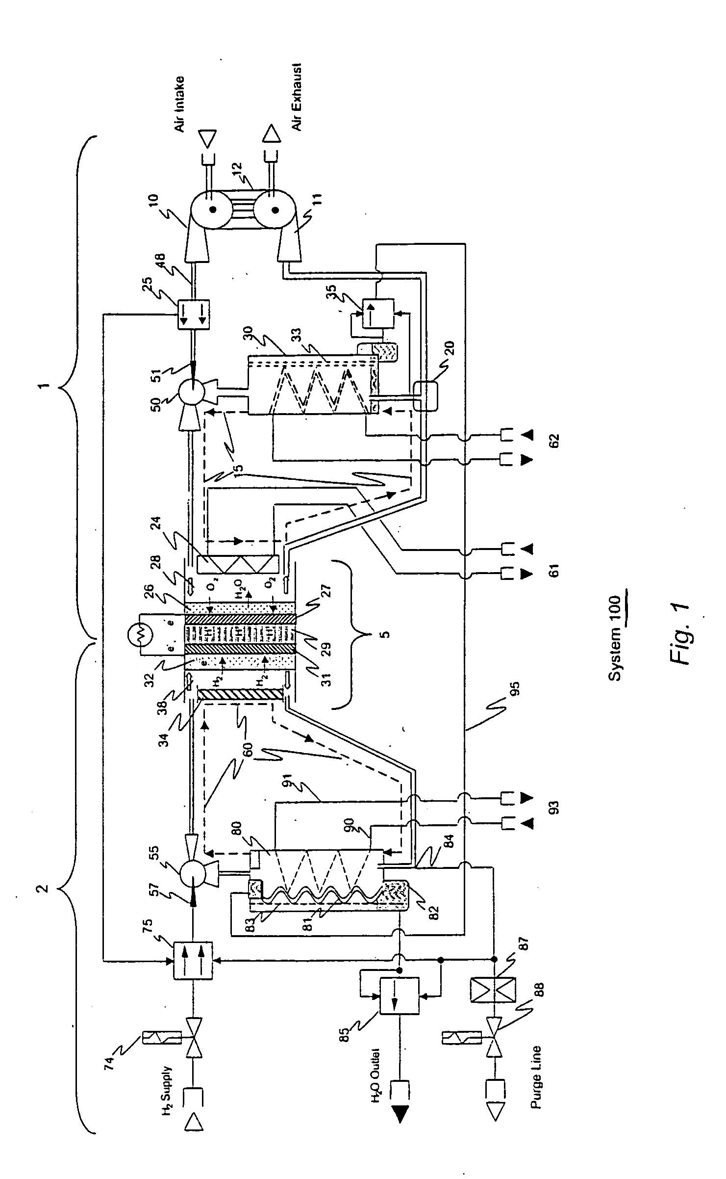
[0037] The invention is an electrochemical generator based on fuel cells, such as hydrogen-air fuel cells with solid polymer proton exchange membranes (PEM) that can be used in mobile or stationary applications. Generators based on the invention provide higher reliability and higher efficiency as compared to conventional fuel cells, particularly under rapid and widely varying power demands, such as those encountered for typical automotive applications.

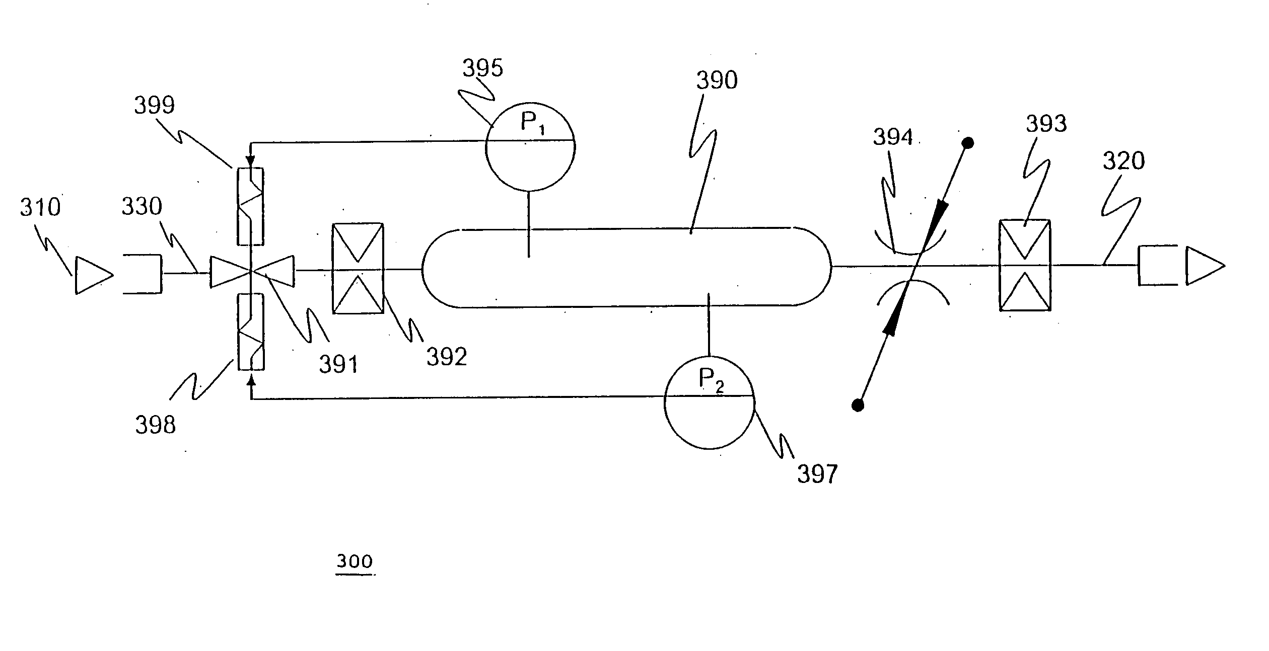
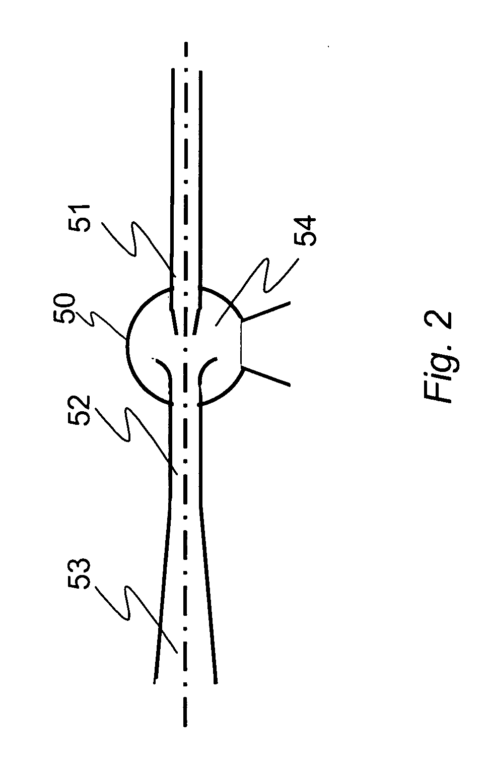
[0038] A recirculating reagent fuel-cell includes an ion-exchange membrane interposed between an anode and cathode anode to form a membrane / electrode assembly (MEA), the MEA interposed between a fuel gas diffusion layer and an oxidant gas diffusion layer. An oxidant and fuel flow network are provided having an input portion for supplying reagent and an output portion for removing excess reagent and reaction byproducts after electrochemical reaction. At least one of the oxidant flow network and fuel flow network includes a feedback con...


PUM

PropertyMeasurementUnit
surface areaaaaaaaaaaa
voltageaaaaaaaaaa
surface areaaaaaaaaaaa

Abstract

A recirculating reagent fuel-cell includes an ion-exchange membrane interposed between an anode and cathode anode to form a membrane/electrode assembly (MEA), the MEA interposed between a fuel gas diffusion layer and an oxidant gas diffusion layer. An oxidant and fuel flow network are provided having an input portion for supplying reagent and an output portion for removing reagent after electrochemical reaction. At least one of the oxidant flow network and fuel flow network includes a recirculation loop, the recirculation loop feeding back a portion of the fuel or oxidant after electrochemical reaction to their respective input portion. The fuel flow network can include a water vapor condenser to extract water from the cathodes in proportion to the external load on the fuel cell stack and the fuel flow network can include an evaporator, where water is fed to the evaporator in the fuel loop from the condenser in the oxidant feed loop.

Description

CROSS-REFERENCE TO RELATED APPLICATIONS [0001] This application claims the benefit of U.S. Provisional Application No. 60 / 519,184 entitled “HYDROGEN-AIR ELECTROCHEMICAL GENERATOR BASED ON FUEL CELLS WITH SOLID-POLYMER ELECTROLYTE” filed on Nov. 12, 2003, the entirety of which is incorporated herein by reference.STATEMENT REGARDING FEDERALLY SPONSORED RESEARCH OR DEVELOPMENT [0002] Not applicable. FIELD OF THE INVENTION [0003] This invention relates to fuel cell assemblies and, more particularly to fuel cells having integrated feedback for regulation of water as well as fuel and oxidant supplied thereto. BACKGROUND OF THE INVENTION [0004] Fuel cells hold great promise for commercial use in mobile and stationary power supply systems. Fuel cells electrochemically convert fuels and oxidants to electricity. Fuel cell types include Alkaline Fuel Cells (AFC), Molten Carbonate Fuel Cells (MCFC), Phosphoric Acid Fuel Cells (PAFC), Proton Exchange Membrane Fuel Cells (PEMFC or PEM), Solid Oxi...

Claims


Application Information

Patent Timeline
Patent Type & Authority Applications(United States)
IPC IPC(8): H01M2/14H01M4/94H01M8/02H01M8/04H01M8/10
CPCH01M8/04097Y02E60/50Y02E60/523H01M8/1002H01M8/1007H01M8/04783
Inventor GURIN, VICTORNOVAK, PETER
Owner ULTIMATE COMBUSTION
Why Eureka
Try Eureka