
Exhaust muffler for internal combustion engines

a technology for exhaust mufflers and internal combustion engines, which is applied in the direction of exhaust treatment, gas passages, gas chambers, etc., can solve the problems of excessive loud and irritating roar, unmuffling operation, and inability to be muffled, so as to improve thermal stability and operational reliability.

Inactive Publication Date: 2005-05-19
PETRACEK RONALD JAMES
View PDF12 Cites 2 Cited by
  • Summary
  • Abstract
  • Description
  • Claims
  • Application Information

AI Technical Summary

Benefits of technology

[0018] And, an ancillary object of the invention is to improve the thermal stability and operational reliability of the exhaust gas muffler for an internal co

Problems solved by technology

Internal combustion engines common to vehicles, such as automobiles, light trucks and sport utility vehicles, and, particularly those fueled by gasoline, inherently produce a loud and irritating roar through the engine exhaust during operation that, if not muffled, is unbearable to a person's ears.
That noise generation becomes particularly loud and irritating when the gas pedal is quickly depressed, “floored”, to force the engine to rapidly accelerate to a high rpm.
The repetitive expulsion of the hot exhaust gases being forced from each engine cylinder in turn and rapid expansion of those gases into the exhaust manifold generates the engine noise.
Although the OEM muffler dampens the harsh sounds produced at the outlet of the tailpipe below the legal limit for sound, the obstruction created by the chamber wall inside the muffler housing produces a back pressure in the exhaust path from the manifold.
In effect, the back pressure robs the engine of some amount of horsepower that could otherwise be obtained from the engine if the exhaust gas were exhausted directly to the atmosphere.
Unfortunately, the matting often breaks down after prolonged use and is discharged into the tailpipe.
The accumulation of those substances reduces the sound absorbency of the matting and, hence, the ability of the muffler to absorb or dampen the exhaust sound level.
However, although of aid, those additional systems are not for the purpose of muffling engine noise at the exterior below the sound limit and do not do so.
Although solving the problem of exterior noise as might be experienced by a bystander to the vehicle, the muffler should also minimize the engine noise that reaches the interior of the automobile and could be disturbing to the automobile owner, in practice, one finds that OEM mufflers and performance mufflers don't always provide appropriate muffling under all driving conditions.
As example, it is found that the internal combustion engine of many sport utility vehicle produces a sound in the interior of the vehicle that is discomforting, if not irritating, that occurs when the engine is operating at about 2200 rpm, which typically corresponds to driving the automobile at a speed of about sixty miles per hour, a typical cruising speed.
The engine also produces that annoying sound on acceleration as the engine passes through the 2200 rpm speed.
Though the muffler achieves sufficient quietude at other speeds, it appears to produce or allow a resonance inside the vehicle cabin at the 2200 rpm engine speed, which is obviously undesirable.
That sound is disconcerting to most drivers who may think an engine backfire is imminent.
Small pick-up trucks experience a similar problem with cabin sound that the muffler fails to handle when the truck is placed under a heavy load, such as when towing a camper or recreational vehicle, horse trailer or the like.
Muffler durability is also a problem.
One finds that some performance mufflers develop hot spots on the muffler case during engine operation.
That thermal action is likely to lead to a break through in the side of the muffler through which exhaust gases and sound escapes to the exterior.
Those vortexes remain stationary in location and don't readily exit the muffler, producing steady heating at a spot on the side of the muffler that, like a blowtorch, ultimately burns through the metal of the muffler case.
Even before any burn-through occurs, the very high temperatures produced by such hot spots in the performance muffler often results in driver discomfort or increased fuel consumption.
Located on the undercarriage of the vehicle the heat from the muffler is conducted or convected in some measure through the vehicle flooring to the interior of the automobile, which, in the summer, is discomforting to the driver, if automobile air conditioning is unavailable.
But prolonged operation of the air conditioner results in greater gasoline consumption, lowering overall engine efficiency.
The foregoing difficulties were noted in exhaust gas mufflers used for gasoline fueled internal combustion engines.
Operated without a muffler, the sound generated during operation of the diesel engine is typically of an acceptable frequency or timbre, but the sound produced is also uncomfortably loud and must also be muffled.

Method used


Image

  • Exhaust muffler for internal combustion engines
  • Exhaust muffler for internal combustion engines
  • Exhaust muffler for internal combustion engines

Examples


first embodiment

[0059] The exploded view of FIG. 10 to which reference is made provides a better view of the various elements of the embodiment of FIG. 9. A first compartment wall 45 at the inlet end of the muffler is spaced behind circular wall 37 at the front or inlet end of the muffler, and a second compartment wall 47 is located at the outlet end of the muffler spaced in front of circular end wall 41 at the exhaust or outlet end of the muffler. Both compartment walls are circular. Central passage 46 is of a much larger diameter than the diameter of passages 26′ and 27′. Compartment wall 45 contains two circular side passages, 26′ and 27′, better illustrated in FIG. 9, spaced on opposite sides of a central passage 46, but only one of those two circular side passages is visible in FIG. 10. Compartment wall 47 likewise includes two circular passages 29′ and 30′, also better illustrated in FIG. 9, spaced on opposite sides of central passage 48 in the wall, but only one of those side passages 29′ is...

second embodiment

[0064] In a practical embodiment of this second embodiment of the invention the muffler was a 8.621 diameter cylinder and of a length of 20 inches. Compartment wall 45 was 8.5 inches in diameter and was formed in 16 gage aluminized steel sheet, central passage 46 was 4.0 inches in diameter and side passages 26′ and 27′ were 1.5 inches in diameter; and those passages were spaced apart by 6 inches center-to-center with each side passage located 3.0 inches from the central passage measured center-to-center. The rear surface of the wall contained a lip of 0.37 inch height surrounding the central opening. The inlet passage 39 in front wall 37 and outlet passage 43 in rear wall 41 were each 4.0 inches in diameter and those walls were 8.5 inches in diameter. The panels forming the divider baffles 17′, 21′ and 23′ were each 3.875 inches in width and 5.0 inches in length and contained a 2.561 inch slot. The louvered tubular member 13′ was 14 inches in length and of a diameter large enough to...


PUM


Abstract

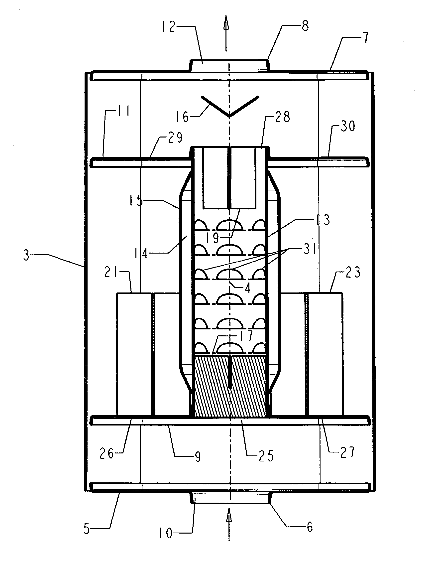
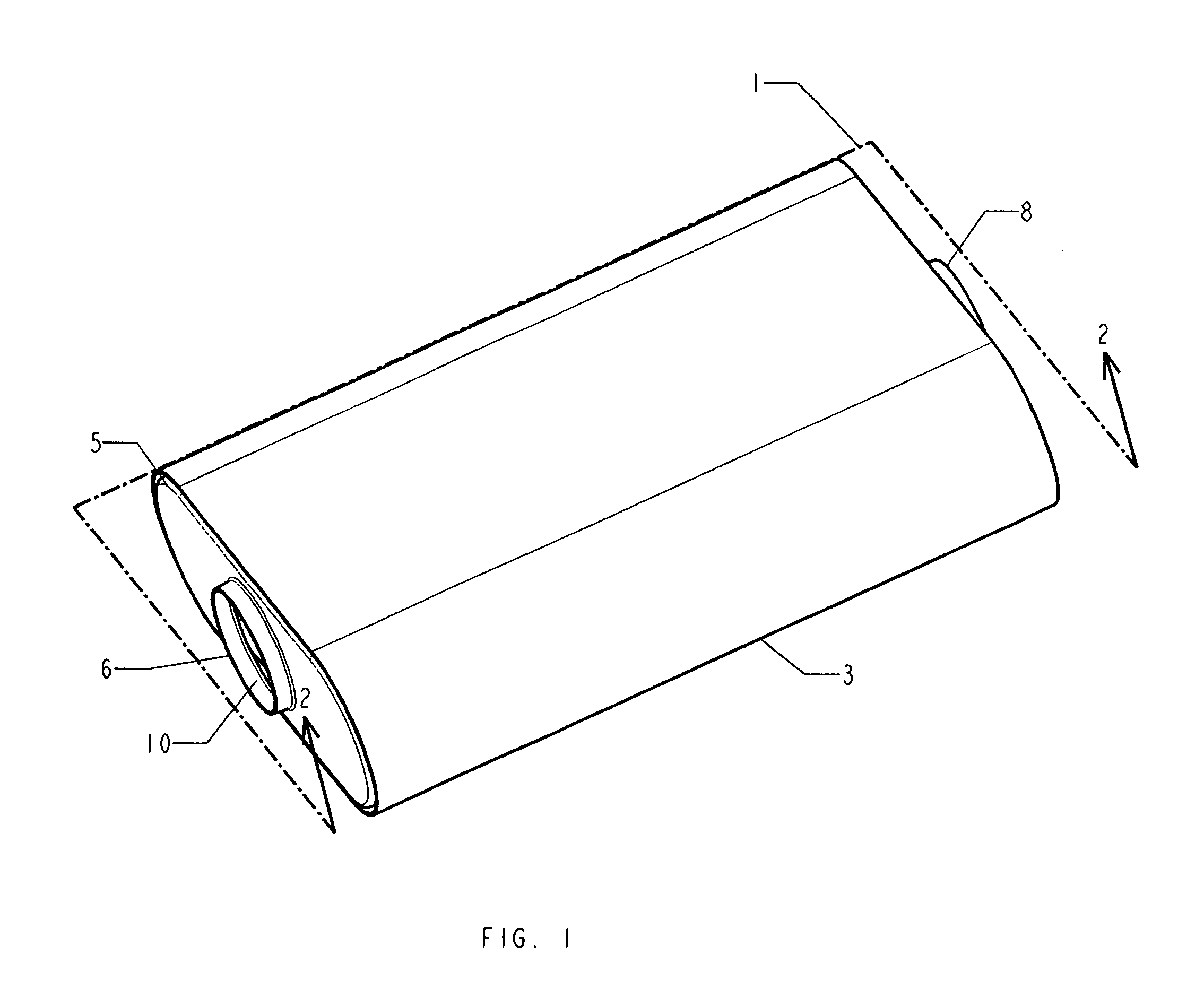
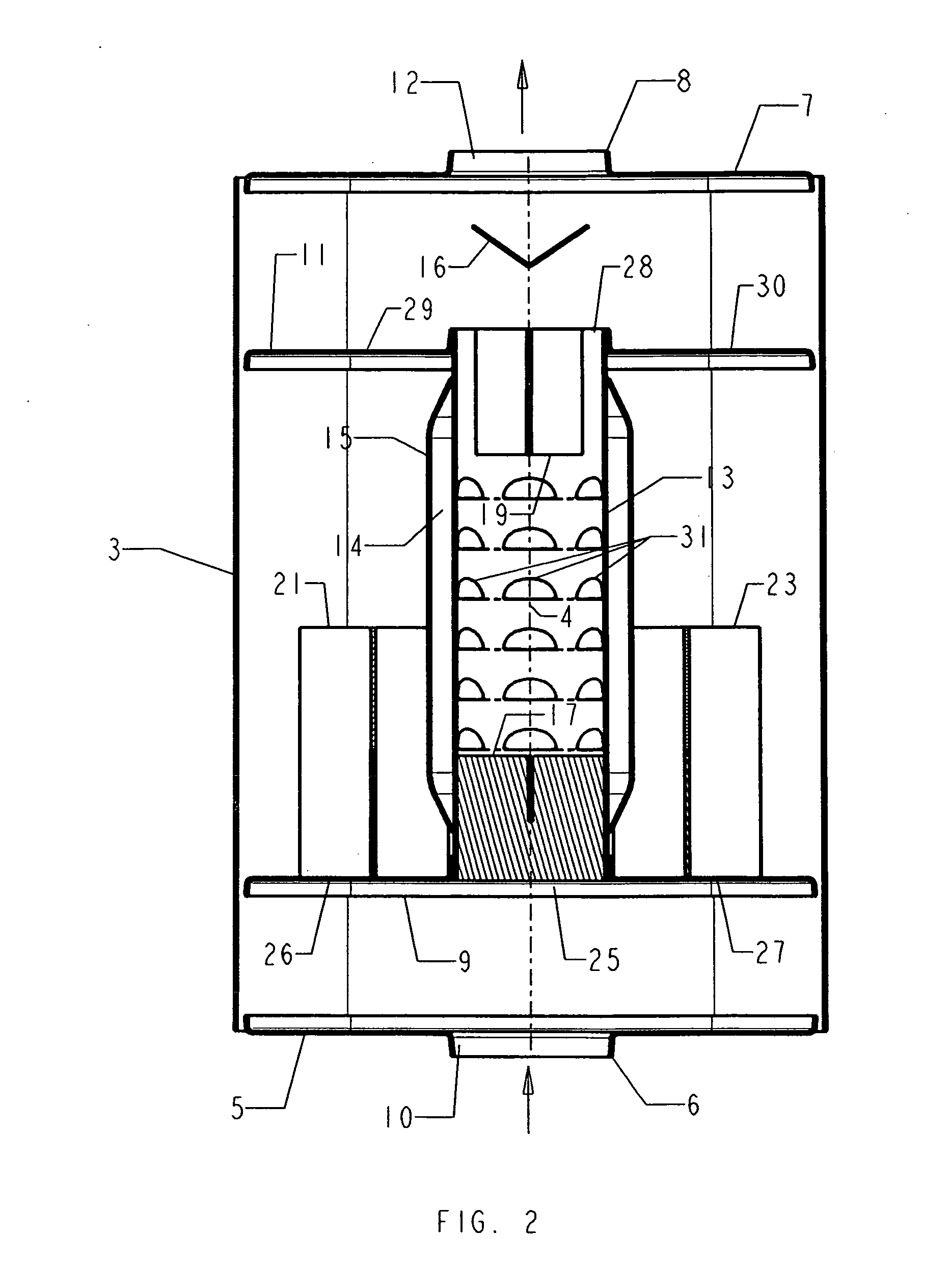
Performance sound is produced with a muffler that includes a casing with front (5, 37), rear (7, 41) and side (3, 35) walls, first (9, 45) and second (11, 47) compartment walls each with a central passage (25, 28, 46, 48) and side circular passages (26, 27, 26′, 27′). The first compartment wall is spaced behind the exhaust gas inlet (6, 39). The second compartment wall is spaced in front of the rear wall. A first divider baffle (21, 21′) divides one side passage in the first compartment wall into a plurality of passages, and a second divider baffle (23, 23′) divides the second side passage in the first compartment wall into a plurality of passages. An elongate louvered tubular member (13,13′) between the first and second compartment walls receives exhaust gas from the first compartment and permits exhaust gas to exit into the second compartment. A third divider baffle (17,17′) divides a portion of the interior of the tubular member into four sectors so exhaust gas entering the tubular member is divided into a plurality of streams.

Description

FIELD OF THE INVENTION [0001] This invention relates to noise reduction in engines, and, more particularly, to exhaust mufflers for attenuating engine exhaust noise generated by internal combustion engines and emitting a performance sound. BACKGROUND [0002] Internal combustion engines common to vehicles, such as automobiles, light trucks and sport utility vehicles, and, particularly those fueled by gasoline, inherently produce a loud and irritating roar through the engine exhaust during operation that, if not muffled, is unbearable to a person's ears. That noise generation becomes particularly loud and irritating when the gas pedal is quickly depressed, “floored”, to force the engine to rapidly accelerate to a high rpm. During the exhaust portion of the four-stroke engine cycle that follows detonation of the fuel and air mixture in the cylinder, the cylinder exhaust valve associated with an engine cylinder opens and the piston, being moved upwardly in the cylinder toward the exhaust...

Claims


Application Information

Patent Timeline
IPC IPC(8): F01N1/00F01N1/02
CPCF01N1/006F01N1/02F01N2530/04F01N2490/04F01N2240/20
Inventor PETRACEK, RONALD JAMES
Owner PETRACEK RONALD JAMES
Learn More