Internal combustion engine fuel supply system

Inactive Publication Date: 2005-06-02
NUCELLSYS
View PDF14 Cites 18 Cited by
  • Summary
  • Abstract
  • Description
  • Claims
  • Application Information

AI Technical Summary

Benefits of technology

[0006] The present system includes a hydrogen generator to produce a hydrogen-rich fuel for combustion in an internal combustion engine. The hydrogen-rich fuel may also be used in a downstream DeNOx catalytic con

Problems solved by technology

For conversion of hydrocarbon fuels, similar amounts of energy have to be transferred at significantly higher temperatu

Method used


Image

  • Internal combustion engine fuel supply system
  • Internal combustion engine fuel supply system

Examples


Embodiment Construction

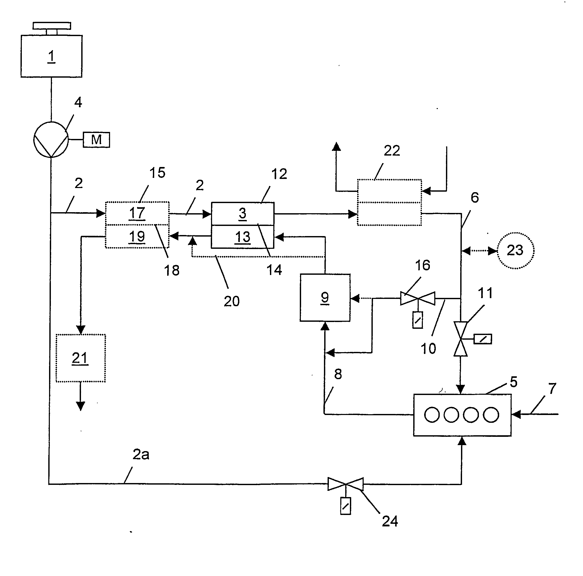
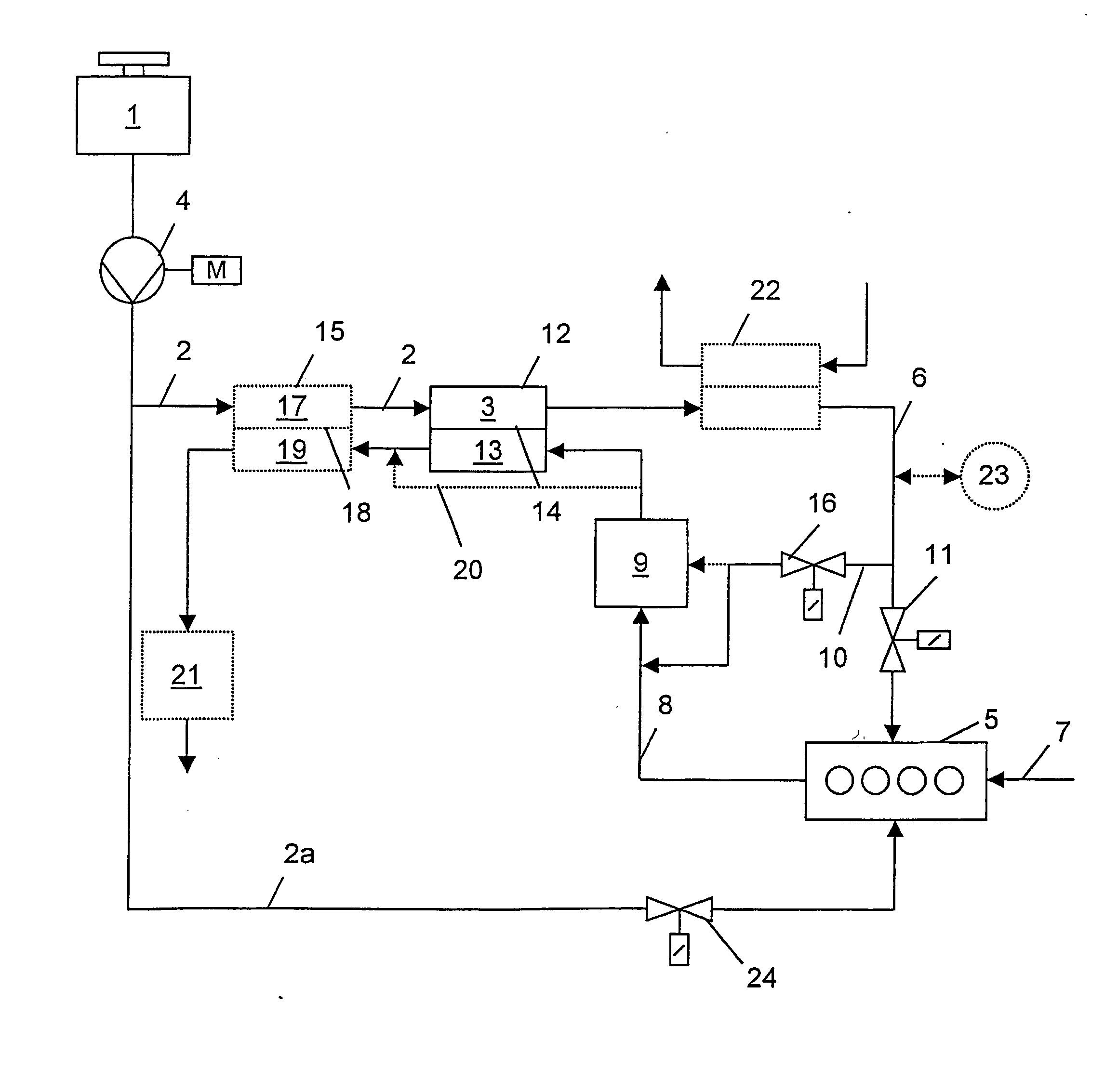
[0016] Raw fuel, preferably in liquid form, is carried in a vehicle in a tank 1, and is fed to a hydrogen generator 3 (e.g. a reformer) by a raw fuel feed line 2. Raw fuel feed line 2 contains a pump 4, which pumps and possibly meters the raw fuel. In hydrogen generator 3, an endothermic reaction converts the raw fuel into a gaseous hydrogen-rich fuel, which is then supplied to an internal combustion engine 5 through a hydrogen-rich fuel feed line 6. To regulate the amount of hydrogen-rich fuel supplied, the hydrogen-rich fuel feed line is equipped with a first valve 11. Air required for combustion is supplied to internal combustion engine 5 through an-intake line 7. After combustion, the exhaust is discharged through an exhaust line 8.

[0017] Exhaust line 8 contains an exhaust purification system 9, preferably a DeNOx catalytic converter, in which nitrogen oxides contained in the exhaust are reduced to nitrogen using reducing agents present in the exhaust.

[0018] To supply or to in...


PUM


Abstract

A system to supply hydrogen-rich fuel to an internal combustion engine, whereby a hydrogen-rich gas is produced from a liquid raw fuel by a hydrogen generator. The exhaust line of the internal combustion engine contains an exhaust purification system, such as a DeNOx catalytic converter, which is at least temporarily supplied with hydrogen-rich gas through a bypass line. In addition, the exhaust line is in thermal contact with the hydrogen generator in order to recover thermal energy.

Description

FIELD OF THE INVENTION [0001] The invention concerns a system for supplying fuel to an internal combustion engine. DESCRIPTION OF THE RELATED ART [0002] A goal in the development of motor vehicles with internal combustion engines today is the reduction of fuel consumption and carbon dioxide emissions. It is also desired to reduce other pollutants in the exhaust, in particular nitrogen oxides (NOx). [0003] Motor vehicles with cracking carburetors, in which hydrocarbon fuels are converted by a partial oxidation device prior to entering the internal combustion engine, are well known. However, this conversion process typically requires temperatures over 800° C., resulting in the formation of soot particulates. In addition, the exothermic nature of the reaction leads to an energy loss during the chemical conversion. [0004] DeNOx (nitrogen oxide removal) catalytic converters, which reduce nitrogen oxides in the exhaust by converting the nitrogen oxides to nitrogen with a suitable catalyst...

Claims


Application Information

Patent Timeline
IPC IPC(8): B01D53/94F01N3/20F02B51/02
CPCB01D53/9431F01N3/2066Y02T10/24F01N2610/04F02B2201/064F01N2610/03Y02A50/20Y02T10/12
Inventor BENZ, UWEDIETRICH, GUENTHERMEGEDE, DETLEF ZUR
Owner NUCELLSYS
Why Eureka
Try Eureka