Imprinting machine and imprinting method

a printing machine and imprinting technology, applied in the field of printing machines and imprinting methods, can solve the problems of lithography technique getting close to a limit, affecting the processing speed of substrates, and requiring a lot of time for forming patterns, so as to prevent the breakage of substrates and molds, and reduce the speed of substrate processing

Inactive Publication Date: 2005-06-02
HITACHI PLANT TECH LTD
View PDF9 Cites 94 Cited by
  • Summary
  • Abstract
  • Description
  • Claims
  • Application Information

AI Technical Summary

Benefits of technology

[0048] Further, the pressurizing mechanism pressurizes to a predetermined pressure on the basis of at least two stages of steps. Accordingly, it is possible to restrict a rapid pressure change generated in the substrate and the mold, and it is possible to prevent the substrate and the mold from being broken. Further, since two or more molds and substrates are simultaneously processed in the different steps, a processing speed of the substrate is improved. Further, the pressurizing unit is constituted by an elevating mechanism for sliding the stage portion, and a pressurizing mechanism for applying a load to the substrate and the mold, the elevating mechanism has a motor serving as a power source, and the pressurizing mechanism has an air cylinder serving as a power source. Accordingly, it is possible to improve the pollution on the substrate and the mold surface caused by the oil leakage from the lot portion at a time of pressurizing such as in the hydraulic mechanism. As a result, the defect of the pattern is improved at a time of imprinting, and it is possible to imprint at a high accuracy.
[0049] In accordance with the present invention, since the micro and nanometer size structure is formed on the substrate, the step of pressuring the mold and the substrate, and the step of peeling the mold from the substrate are constituted by the independent units, and the processes in the respective units can be independently executed by moving the mold and the substrate in the integrated state at a time of moving from the pressurizing step to the peeling step, the processing efficiency is improved.

Problems solved by technology

However, a working method gets close to a wavelength of a light source of a light exposure, and the lithography technique gets close to a limit.
Accordingly, the more the pattern to be drawn is, the more the exposing (drawing) time is, so that there is a disadvantage that a lot of time is required for forming a pattern.
Therefore, in proportion as an integration degree is dramatically increased to 256 megabyte, 1 gigabyte and 4 gigabyte, a pattern forming time is dramatically improved by just that much, so that there is a fear that a throughput is significantly deteriorated.
Accordingly, there is a disadvantage that a cost of the apparatus is increased.
Since the substrate and the heat block are fixed continuously by a peeling apparatus, there is a problem that steps after the pressurization, for example, a peeling step, a inspecting step of the mold, a cleaning step and the like, are all brought under control, and a throughput is extremely deteriorated.

Method used


Image

  • Imprinting machine and imprinting method
  • Imprinting machine and imprinting method
  • Imprinting machine and imprinting method

Examples


embodiment 1

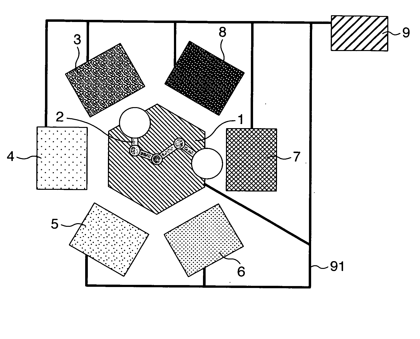
[0096]FIG. 1 shows a schematic plan view of an arrangement of the respective units of the imprinting apparatus in accordance with the present invention. The following micro pattern imprinting experiments are executed by using the imprinting apparatus in accordance with the present embodiment.

[0097] The present imprinting apparatus is constituted by a substrate carrying in and carrying out unit 3, a mold storing unit 4, an alignment unit 5, a pressurizing unit 6, a peeling unit 7 and a mold cleaning unit 8, which are arranged around a conveying unit 1. Further, the respective units are connected to a control unit 9 by a connecting cable 91. In the substrate carrying in and carrying out unit 3, there are set a plurality of substrates (not shown) in which a polystyrene resin membrane having a thickness of 500 nm is formed on a silicone wafer having a diameter of 6 inch φ. The substrate is moved to each of the units in accordance with each of the steps by a robot arm 2.

[0098] A descri...

embodiment 2

[0120] The same imprinting experiment as the embodiment 1 is executed by an imprinting apparatus using a photo cure type pressurizing unit shown in FIG. 9. In this case, the substrate employs a substrate obtained by applying PKA01 (produced by TOYO GOSEI) corresponding to a liquid photo cure type resin onto the silicone wafer having a diameter of 6 inchφ in accordance with a spin coat method.

[0121] A quartz mold 64 and a substrate 65 which are aligned by the alignment unit are moved to the stage side adapter 28 so as to be adsorbed. Next, an entire stage is moved upward by the stage elevating drive motor until the quartz mold 64 is in contact with a mold fixing jig 62 fixed to the frame 35 so as to pressurize and closely attach the substrate 65 and the quartz mold 64.

[0122] Next, an ultraviolet ray having a power of 1000 mJ / cm2 is irradiated by an ultraviolet ray lamp 61 on which an extra-high pressure mercury lamp is mounted. Next, the stage is moved downward, the sample in which...

embodiment 3

[0124] The same imprinting experiment as the embodiment 1 is executed by using an imprinting apparatus in which a mold inspecting unit 95 and a substrate inspecting unit 96 are added to the imprinting apparatus in accordance with the embodiment 1 shown in FIG. 10. In FIGS. 10 and 11, the same reference numerals as those in FIGS. 1 and 8 denote the same elements. FIG. 11 shows a flow chart paying attention to the movement of the metal mold substrate 92 and the mold 93 at that time. The present flow chart is described for explanation in such a manner that only one set of substrate and mold are moved, however, plural sets of substrates / molds are actually moved and processed simultaneously.

[0125] First, the substrate 92 in which the resin membrane is formed is moved from the substrate carrying in and carrying out unit 3 to the alignment unit 5 by the conveying robot arm 2 (FIG. 11A→FIG. 11B).

[0126] Next, the mold 93 is moved from the mold storing unit 4 to the alignment unit 5 by the ...


PUM

PropertyMeasurementUnit
sizeaaaaaaaaaa
thicknessaaaaaaaaaa
thicknessaaaaaaaaaa

Abstract

An object of the invention is to execute an imprinting process at a higher speed and a higher accuracy, in an imprinting apparatus. In an imprinting apparatus for contacting and pressurizing a mold having a micro concavo-convex structure formed on a surface thereof to a substrate surface in order to form a micro and nanometer size structure on a substrate, a step of pressurizing the mold and the substrate and a step of peeling the mold from the substrate are constituted by independent units, the mold and the substrate are moved in a closely attached state at a time of moving from the pressurizing step to the peeling step, and preferably at least two sets of molds and substrates are processed by the different steps simultaneously or a temporarily overlapped manner.

Description

TECHNICAL FIELD [0001] The present invention relates to an imprinting method of forming a micro and nano structure body on a substrate by using a mold in which micro concavity and convexity having a nanometer unit or a micrometer unit is formed on a surface, and an imprinting machine for executing the method. BACKGROUND ART [0002] In recent years, micronization and integration of a semiconductor integrated circuit are developed, and a high precision of a photolithography apparatus is promoted as a pattern imprinting technique for achieving a micro-fabrication. However, a working method gets close to a wavelength of a light source of a light exposure, and the lithography technique gets close to a limit. Accordingly, in order to accelerate further the micronization and the high precision, an electron beam drawing apparatus corresponding to a kind of charged particle beam apparatus is employed in place of the lithography technique. [0003] A pattern formation using an electron beam empl...

Claims


Application Information

Patent Timeline
Patent Type & Authority Applications(United States)
IPC IPC(8): B81C99/00B29C35/08B29C43/02G03F7/00
CPCB82Y10/00G03F7/0015G03F7/0002B82Y40/00
Inventor OGINO, MASAHIKOMIYAUCHI, AKIHIROKUWABARA, KOUSUKEANDO, TAKASHITAKAHASHI, KAZUO
Owner HITACHI PLANT TECH LTD
Why Eureka
Try Eureka