Composition of a thermaly insulating coating system

a technology of thermal insulation and coating system, applied in the direction of coatings, ceramic layered products, transportation and packaging, etc., to achieve the effect of reducing thermal conductivity, high infra red reflectivity, and reducing heat transfer

Inactive Publication Date: 2005-06-16
ANTHONY DAVID SKELHORN
View PDF4 Cites 133 Cited by
  • Summary
  • Abstract
  • Description
  • Claims
  • Application Information

AI Technical Summary

Benefits of technology

[0017] The purpose of the present invention is to provide a composition description that allows a “Coating System” comprised of either one or two layers, being a “Thermal Coating” and, optionally, a “Thermal Primer”. The Coating System is designed with high infra red reflectivity plus reduced thermal conductivity, and may be formulated to any desirable color. This approach is especially beneficial if darker colored coatings are desired, since these are often considered to be most heat absorbing. The Coating System is designed to reduce heat transfer from the environment to the substrate that is protected by the Coating System by formulating to reduce both radiant and conductive heating. The Coating System provides a mechanism for reducing absorption of electromagnetic radiation in the infra red region of the spectrum, commonly described as heat, plus use of materials which reduce conductive heat transfer. The system is designed to act as an insulating material in applications where infra red radiation levels are significant, such as bright sunlight.

Problems solved by technology

Furthermore, the spheroidal geometry of such micro-spheres restricts heat transfer to point-to-point conduction there between.

Method used


Image

  • Composition of a thermaly insulating coating system
  • Composition of a thermaly insulating coating system
  • Composition of a thermaly insulating coating system

Examples


example 1

[0055] A number of extender pigment materials were used to prepare single pigment paints at a Pigment Volume Concentration of 30% (Table 3).

TABLE 330% PVC Single Pigment Formulation for measurementof Thermal PropertiesMaterialWeight (g)% SolidsDry VolumeM-444 Acrylic Resin1405070Defoamer BYK-0180.250Superwet S22 surfactant0.250Busperse 39 dispersant1.850Pigment30 × SG10030Mix under high shear using a Dispermat mixer at 5000 rpm until dispersedSpecificPigment wtManufacturerPigmentGravityper 140 resinUS SilicaSilcosil 1252.6579.5IneosMD101 Fume Silica2.4072.0OmyaOmyacarb 102.6880.4Specialty MineralsMarblewhite #3252.6579.5Mississippi LimeMagnum Gloss PCC2.8585.5ImerysGlomax JDF2.6278.6EngelhardSatintone W2.6278.6ImerysMetaStar2.6278.6ImerysNeoGen 20002.6278.6ImerysNeoGen FTE2.6278.6Buckman LabsBusan 11-M 13.3099.0Sachtleben ChemieBlanc Fixe Micro4.36130.8Sachtleben ChemieLithopone DS4.30129.0KadoxKadox 9155.60168.0HaloxStrontium Zinc3.2497.2PhosphosilicateLuzenacNicron 554 Talc2.858...

example 2

[0058] Single pigment coatings were prepared as described in Table 3. The paint samples were used to prepare a paint draw-down on siliconized release paper using an 8-path precision wet film applicator at 3, 6, 9 and 12 mils (75, 150 and 225 and 300 microns approximately) application thickness. The coatings were allowed to dry for 1 week. Film Thickness was measured using a “Mitutoyo Digimatic” micrometer.

[0059] Thermal conductivity measurements were made using a T-C 1000 Thermal Comparator (Lafayette Instrument Company). The method uses an insulated mass that has fine temperature control using a controlled electrical heating element. For this study the mass was heated to 100±0.1 degrees Celsius while ambient temperature was 25 degrees Celsius. The mass has a conical tip (insert of FIG. 4) that contains a thermocouple for local temperature measurement, all of which is enclosed in an insulated chamber, through which only the tip protrudes. This tip is presented to the test media and...

example 3

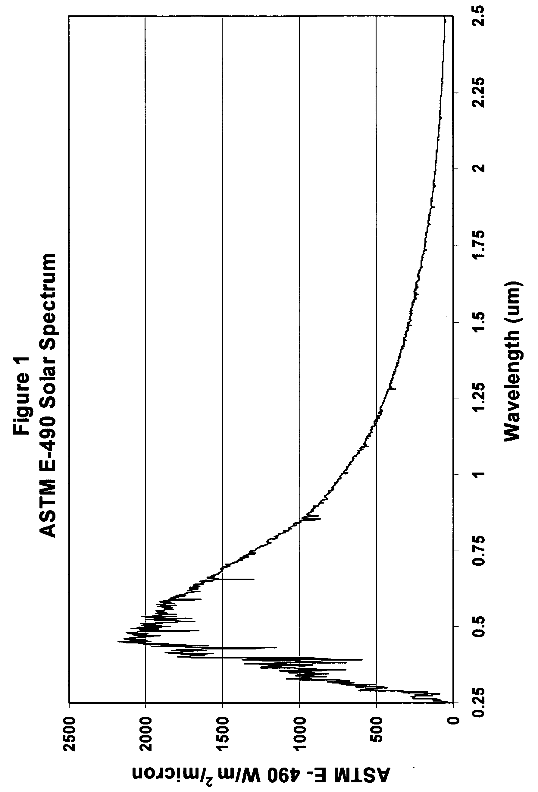
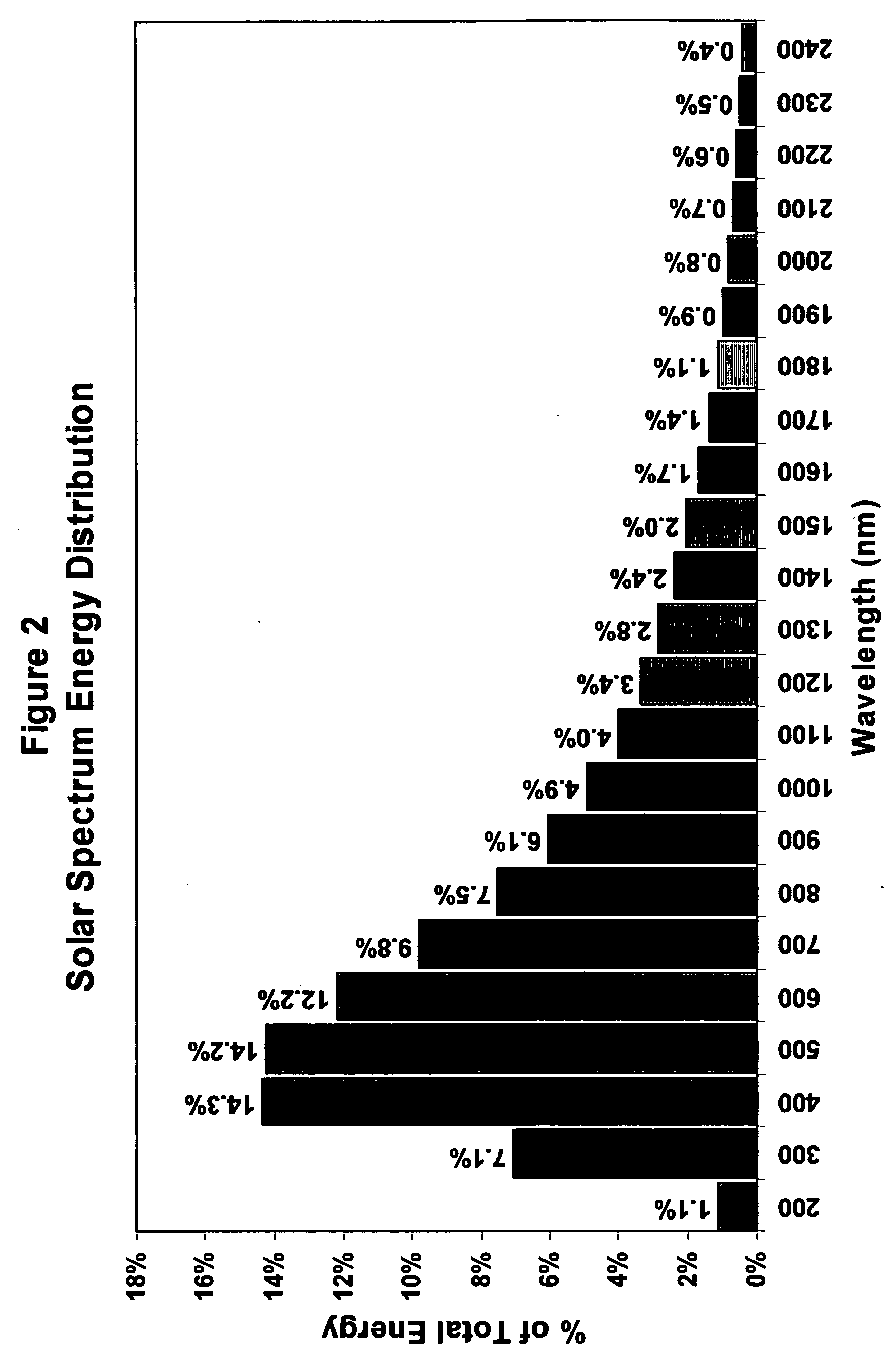
[0063] Two “Thermal Coatings” were prepared and color matched to a typical industrial standard for the same application. The two “Thermal Coatings” were based on 1) a reflective pigment system and, 2) a reflective pigment plus an extender pigment having an “infra red reflectivity ratio” greater than 1.0 (NeoGen FTE—Table 6). The paint samples were used to prepare paint draw-downs on Leneta drawdown cards, type 5DX, using an 8-path precision wet film applicator at 3 mils (75 microns) application thickness. The coatings were allowed to dry for 1 week after which reflectance values were determined for wavelengths from 250 nm to 2500 nm at 10 nm intervals, using the black background area of the Leneta card. The reflectance spectra from 250 nm to 2500 nm are shown in FIG. 5 for these two coatings compared to the conventional material of the same color. These spectra demonstrate the complementary role of reflective extender pigment on reflectivity in the infra red region of the solar spec...


PUM

PropertyMeasurementUnit
particle sizeaaaaaaaaaa
temperatureaaaaaaaaaa
wavelengthsaaaaaaaaaa

Abstract

A composition for a Coating System (paint) which forms an insulating material being designed to both reflect infrared radiation and have reduced thermal conductivity. The coating system may be either a single Thermal Coating or may be a Thermal Coating used in combination with a Thermal Primer. The Thermal Coating is formulated using conventional techniques and a resin used in paint manufacture, but utilizes primary pigments and extender mineral pigments which preferentially reflect in the infra red area of the solar spectrum. A method of characterizing particulate materials for their infra red reflectivity is described, which provides a means for preferential selection of particulate additives based on their relative visible light and infrared reflectivity. Additionally the incorporation of hollow micro-spheres is desired to reduce thermal conductivity. The Thermal Primer is designed to provide adhesion between the Thermal Coating and the substrate on which it is applied and uses conventional techniques to achieve those properties. However it has been found advantageous to incorporate hollow micro-spheres with low thermal conductivity, such as glass, ceramic or polymeric micro-spheres and/or an extender pigment with low thermal conductivity such as calcined clay to further reduce heat flow through the Coating System.

Description

STATEMENTS AND REFERENCES [0001] Reference: Provisional application No.60 / 525,683 filing date Dec. 1, 2003, Composition of a thermally insulating coating system, Anthony D. Skelhorn.BACKGROUND OF INVENTION [0002] Compositions that may be used to thermally insulate other materials, especially from the effect of intense sunlight, have a number of potential applications: Examples include among others: [0003] a) Insulation of structures (e.g. a house or hotel) to reduce energy consumption, especially during summer months in southern regions. [0004] b) Insulation of flooring material (such as wood or concrete) to reduce the temperature, thus allowing, for example, bare-foot passage on a patio or deck. [0005] c) Insulation of heat sensitive equipment such as is used in military and civilian applications, allowing improved operational efficiency by reducing the influence of heat on internal components under arduous conditions, such as desert environment. [0006] The invention describes a me...

Claims


Application Information

Patent Timeline
Patent Type & Authority Applications(United States)
IPC IPC(8): C04B14/20C04B16/08C04B26/02C04B28/02C09C1/02C09D5/00C09D7/12
CPCC04B26/02Y10T428/25C04B2111/00482C04B2111/00612C04B2111/28C08K3/34C08K7/22C09D5/002C09D5/004C09D7/1216C09D7/1291C04B28/02Y10T428/254Y10T428/252C04B14/042C04B14/10C04B14/20C04B14/24C04B14/301C04B16/08C04B2103/54C09D7/61C09D7/70
Inventor SKELHORN, ANTHONY DAVID
Owner ANTHONY DAVID SKELHORN
Why Eureka
Try Eureka