
Time-of-flight mass spectrometer for monitoring of fast processes

a mass spectrometer and time-of-flight technology, applied in mass spectrometers, separation processes, particle separator tube details, etc., can solve problems such as power loss

Inactive Publication Date: 2005-06-16
IONWERKS
View PDF12 Cites 60 Cited by
  • Summary
  • Abstract
  • Description
  • Claims
  • Application Information

AI Technical Summary

Benefits of technology

[0088] The photo-fragmentation procedure is particularly advantageous because it can easily be turned on and off to give a flexibility to the fragmentation. The photon flux can be conveniently applied only at time when a desired mass or mobility or chromatographically separated collection of ions is presented to the fragmentation region (which can be before, within, or after the focusing region (25); see FIGS. 4, 5, and 6). This flexibility is further enhanced by photon optics which will form the photon beam into a line source which will maximally overlap with the parallel ion or neutral beamlets within the fragmentation regions. A laser has the advantage of many photons within one short (nanoseconds to femtoseconds) optical pulse temporal width. This can be an advantage in some circumstances when the fluence is so strong from the laser pulse that near simultaneous multiple photon absorption into each ion occurs. It is a further advantage of the invention that the ions to be fragmented are moving relatively slowly so that they are often within the fragmentation region for tens of microseconds. Thus the need for supplying all the photofragmentation photons in one small temporal pulse (i.e., laser) is lifted and less brilliant sources (such as resonance lamps and other sources familiar to those skilled in the art) can be chopped either optically or electrically into a comparable tens of microsecond photon irradiation time so that photoionization or photofragmentation processes are optimized. Thus a continuous photon source can be made to supply the same number of photons as with the laser over the same spatial region but over a longer time.
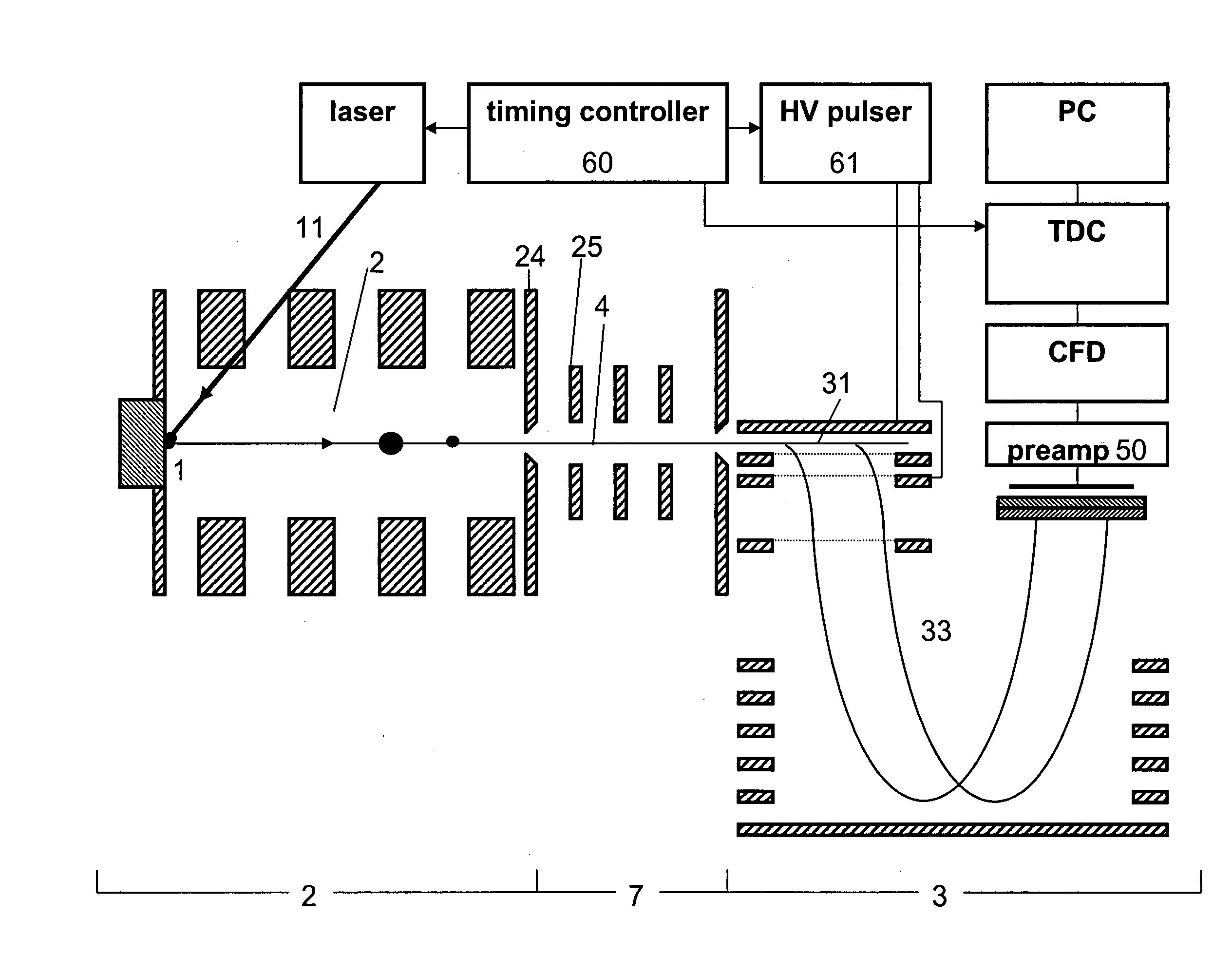
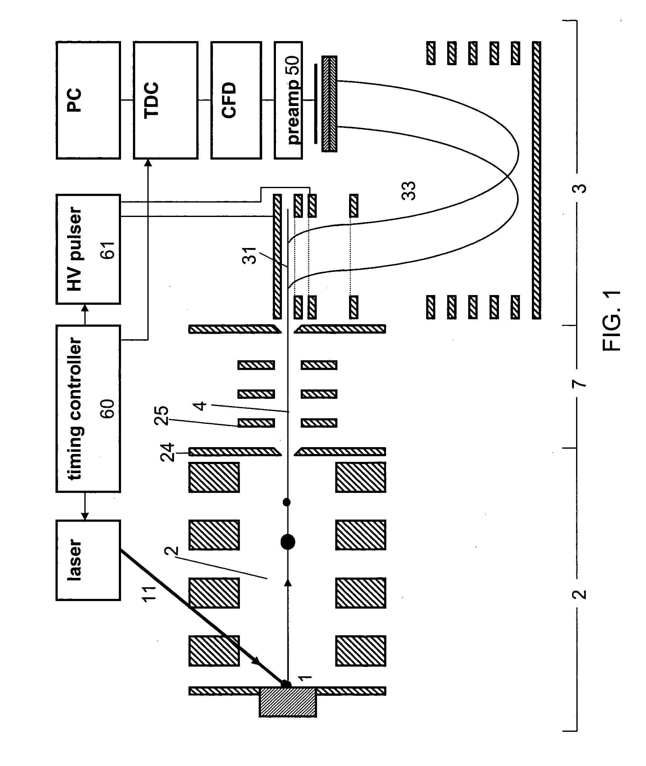
[0089] A further important application of the invention is shown in FIG. 10. This application is useful whether the PSD is titled or not. FIG. 10A is a side view of the apparatus and FIG. 10B is a view along the input direction of the input ion beam into the time-of-flight mass spectrometer. In FIG. 10A and ion source, beam transport optics, optional fragmentation region and ion beam forming optics is represented by (80) which is capable of generating one or more ion beamlets. Within each ion beamlet (82, 83) the ion trajectories are nearly parallel along the direction X of photon ray (70) and Y of alternate photon ray (71) (parallel to planes of the plates in the extraction region (31)) and are also physically separated from each other along Y but are still substantially parallel to each other. This is further seen in the end on view in FIG. 10B also with reference to FIG. 10A where beamlet (81) fills extraction region (31) between positions (5) and (6) while beamlet (82) fills the extractor region between (7) and (8). After a high voltage extraction the ions in beamlet (81) are spatially mapped onto a row of pixels (45) and beamlet (82) is spatially mapped onto another discrete row of pixels (46) which are parallel to axis Y′. In FIG. 10 another row of pixels (44) is unused thus illustrating that this configuration could have up to three beamlets simultaneously resolved each originating from a distinct ion source so that the fast processes in each of three distinct ion sources could be measured and kept separate with one TOF equipped with a multipixel detector (43) comprising rows and columns of pixels. The depiction of two beamlets (81) and (82) in the drawing is for illustrative purposes only and it should be understood that more beamlets are possible and that the limitation on the number of simultaneous beamlets which can be processed is restricted by the practical limitations on the number of discrete pixel rows (44, 45, 46) and the number and parallelism of the beamlets which can be formed by (80) so that the beamlets do not intermix in the extraction region (31) or on the detector (43).
[0090] The configuration in FIG. 10A and FIG. 101B is ideally suited for applications where multiple liquid chromatographic columns feed multiple electrospray ionizers which are each feeding an ion trap the outputs of which are then each gated into discrete IMS channels so that the output of the multiple IMS goes into one mass spectrometer. Ideally, such a trap array could feed each channel of a multichannel IMS spectrometer as described in copending U.S. provisional application 60 / 512,825 of Schultz et al. (to be filed as a regular utility application under attorney docket no. P02863US1) and U.S. application Ser. No. 09 / 798,030 to Fuhrer et al., filed Feb. 28, 2001. Another application would be during microprobe imaging of a surface by a focused ion beam or laser beam in which the microprobe beam would be accurately scanned (electrostatically for the ion beam and by an electro-optic mirror for the focusing laser) between for

Problems solved by technology

Increasing the ion energy is the preferred method, because decreasing the drift length results in a loss of resolving power.

Method used


Image

  • Time-of-flight mass spectrometer for monitoring of fast processes
  • Time-of-flight mass spectrometer for monitoring of fast processes
  • Time-of-flight mass spectrometer for monitoring of fast processes

Examples


Embodiment Construction

[0031] The following discussion contains illustration and examples of preferred embodiments for practicing the present invention. However, they are not limiting examples. Other examples and methods are possible in practicing the present invention.

[0032] As used herein the specification, “a” or “an” may mean one or more, unless expressly limited to one. As used herein in the claim(s), when used in conjunction with the word “comprising”, the words “a” or “an” may mean one or more than one. For example, where an instrument component or method step is called for, it should be taken to include more than one of the same component or method step. As used herein “another” may mean at least a second or more.

[0033] The following discussion contains illustration and examples of preferred embodiments for practicing the present invention. However, they are not limiting examples. Other examples and methods are possible in practicing the present invention.

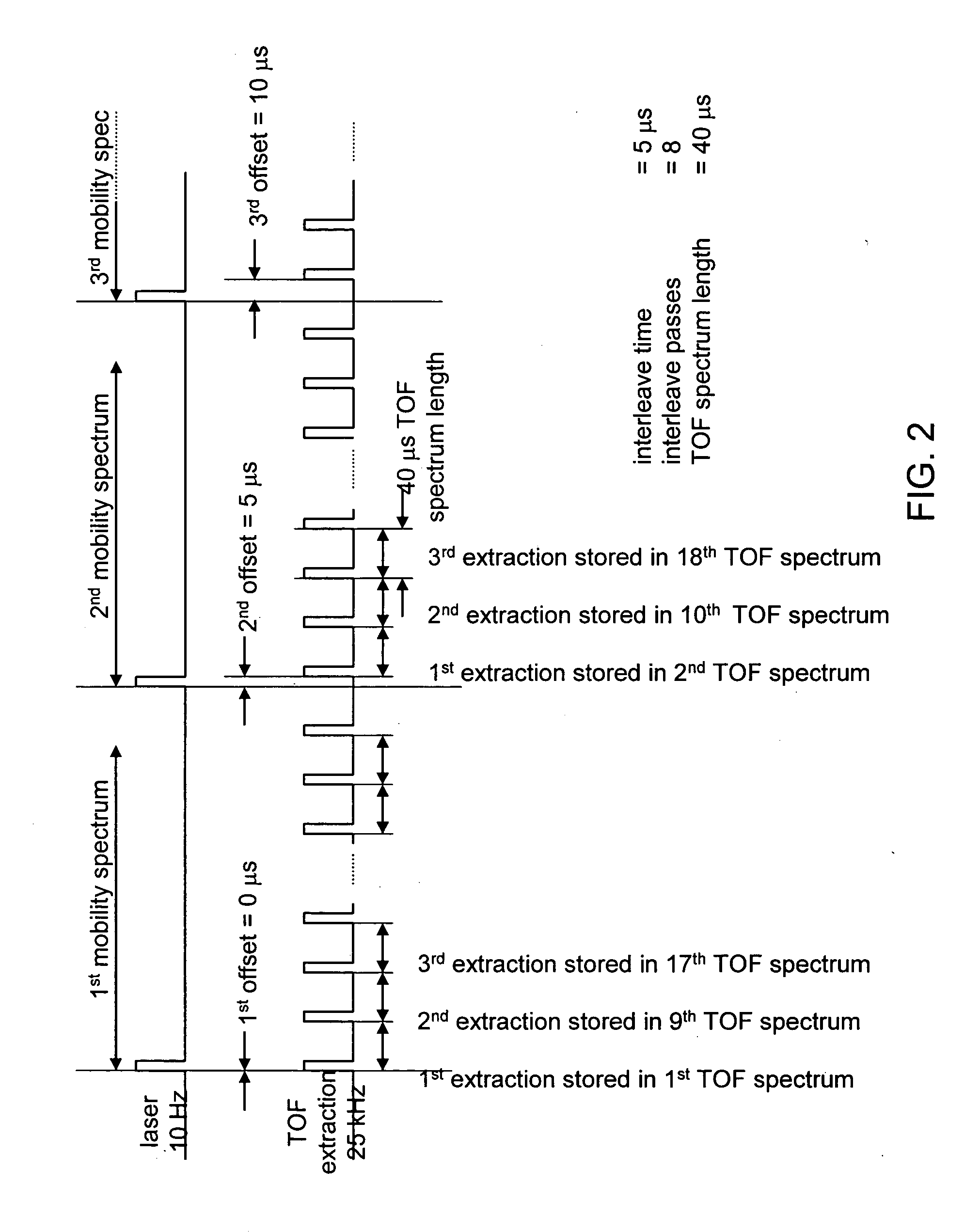
[0034] As defined herein, “interleaved ...


PUM


Abstract

Time-of-flight mass spectrometer instruments for monitoring fast processes using an interleaved timing scheme and a position sensitive detector are described. The combination of both methods is also described.

Description

[0001] This application is a continuation-in part of, and claims priority to, U.S. application Ser. No. 10 / 689,173, filed Oct. 20, 2003, which is a continuation-in-part of U.S. application Ser. No. 10 / 155,291, filed May 24, 2002 and issued as U.S. Pat. No. 6,683,299, and to U.S. Provisional Application 60 / 293,737, filed May 25, 2001.[0002] This work has been funded in whole or in part with Federal funds from the National Institutes of Health, Department of Health & Human Services, NIH Phase II Grant No. 2 R44 RR12059-02A2. The United States government may have certain rights in the invention.FIELD OF THE INVENTION [0003] The invention is a time-of-flight mass spectrometer (TOF) capable of monitoring fast processes. More particularly, it is a TOF for monitoring the elution from an ion mobility spectrometer (IMS) operated at pressures between a few Torr and atmospheric pressure. This apparatus is an instrument for qualitative and / or quantitative chemical and biological analysis. BACKG...

Claims


Application Information

Patent Timeline
Patent Type & Authority Applications(United States)
IPC IPC(8): B01D59/44H01JH01J49/00H01J49/40
CPCH01J49/025H01J49/0059H01J49/40
Inventor FUHRER, KATRINGONIN, MARCGILLIG, KENT J.EGAN, THOMAS F.MCCULLY, MICHAEL I.SCHULTZ, J. A.
Owner IONWERKS
Learn More