Mass Spectrometer

a mass spectrometer and mass range technology, applied in the field of mass spectrometers, can solve the problems of significantly increasing the cost, unable to obtain a duty cycle of 40% or less, and the mass range which can obtain a high duty cycle is extremely limited, so as to achieve high mass accuracy and high sensitivity

Active Publication Date: 2005-06-16
HITACHI HIGH-TECH CORP
View PDF7 Cites 36 Cited by
  • Summary
  • Abstract
  • Description
  • Claims
  • Application Information

AI Technical Summary

Benefits of technology

[0022] (5) In the mass spectrometer of the. (2) or (3) the second linear trap accumulates ions by increasing and decreasing the potential of the end lens disposed at the exit end from the potential on the center axis of the rods to eject them to the time-of-flight mass spectrometer.
[0023] According to the present invention, a mass spectrometer which can analyze a wide mass range with high sensitivity and high mass accuracy.

Problems solved by technology

The above-described Conventional Method 1 has the problem that only a duty cycle of 40% or below can be obtained.
Conventional Methods 2 and 3 have the problem that a mass range which can obtain a high duty cycle is extremely limited.
These significantly increase the cost.
In particular, when using an ADC (Analog-to-digital converter) for data conversion, increased signal pulse width due to the larger detector lowers the mass resolution.

Method used


Image

  • Mass Spectrometer
  • Mass Spectrometer
  • Mass Spectrometer

Examples


embodiment 1

(Embodiment 1)

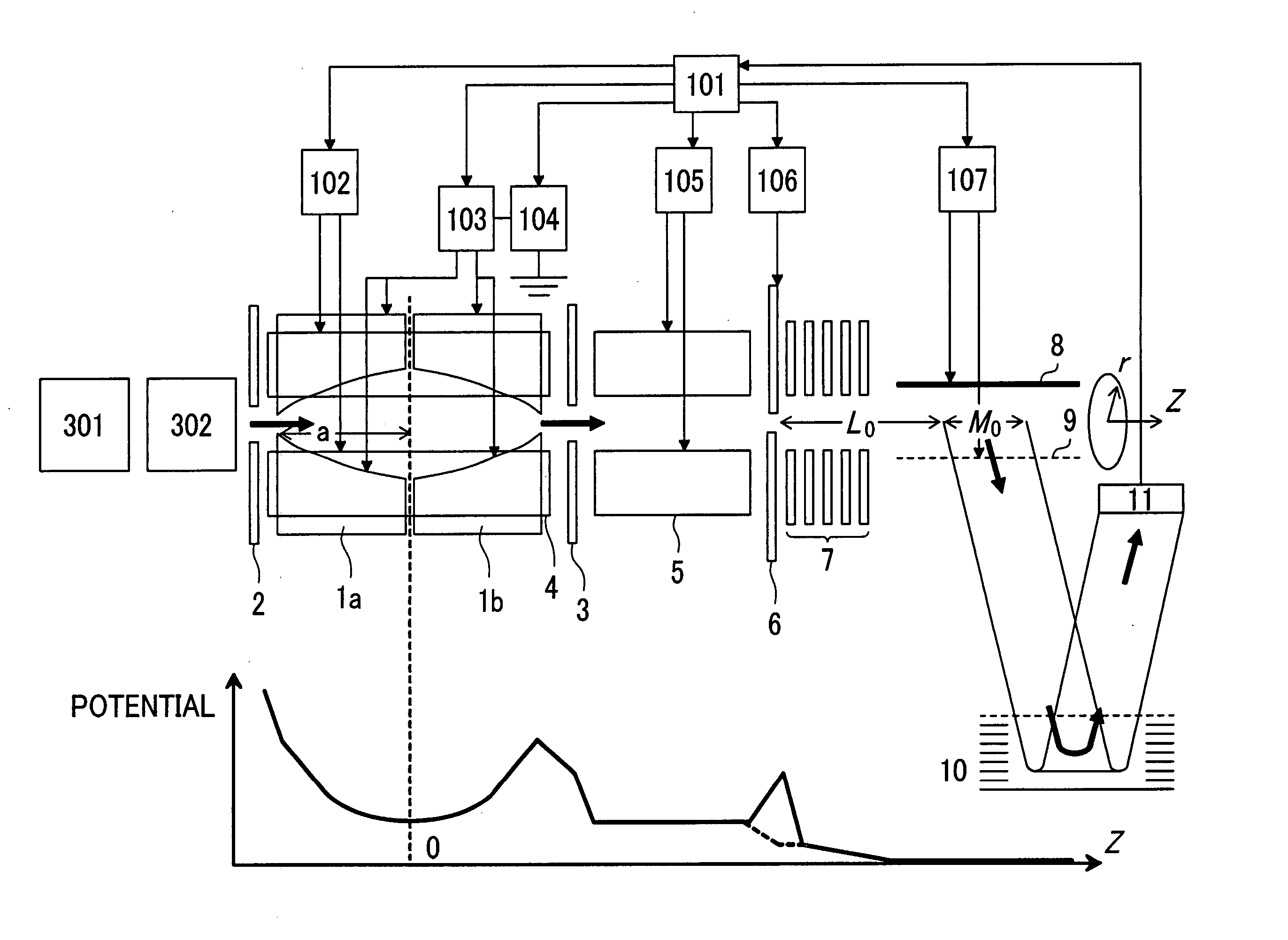
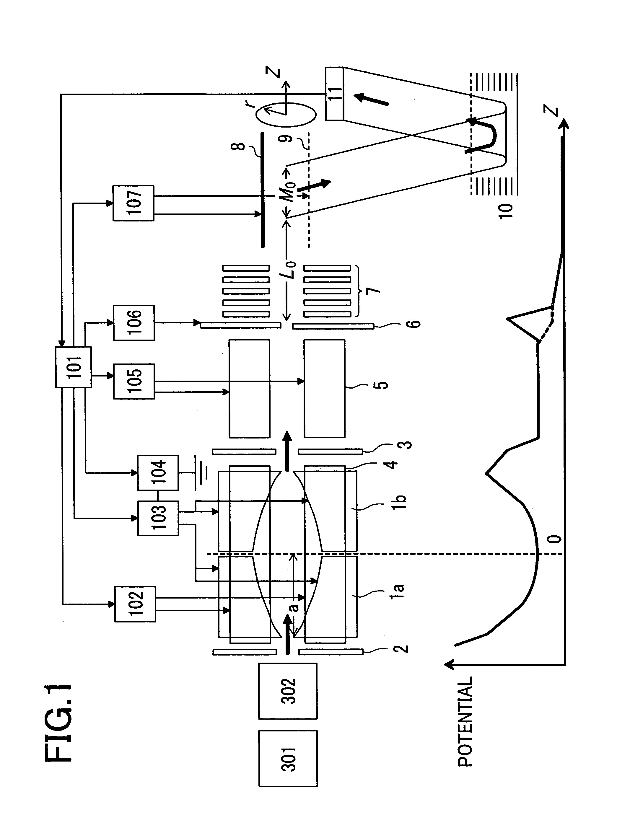
[0043]FIG. 1 shows a block diagram of a time-of-flight mass spectrometer according to a first embodiment of the present invention. The pumping device such as a pump and the buffer gas introducing mechanism are omitted for simplification.

[0044] Ions generated by an ionization source 301 such as an electrospray ionization source, a matrix assisted laser desorption ionization source, an atmospheric pressure chemical ionization source, an atmospheric pressure photoionization source, or an atmospheric pressure matrix assisted laser desorption ionization source are introduced via an ion transfer optics 302 having an octapole, a quadrupole mass filter, or a quadrupole ion trap or a multipole linear trap permitting accumulation, isolation, and dissociation and an inlet electrode 2 into a first linear trap. The detail of the first linear trap is described in the previously described Conventional Method (Patent Document 3).

[0045] The first linear trap has an inlet electrode 2,...

embodiment 2

(Embodiment 2)

[0065] The ion quantity which can be accumulated in the first linear trap is limited. In order not to be affected by space charge, faster measurement is desired.

[0066] A second embodiment of the present invention making measurement faster will be described. The construction of the apparatus is almost the same as the first embodiment (FIG. 1). A supplemental AC power supply 103 can generate the superimposed waveform of a plurality of RF voltages.

[0067]FIG. 9 shows its measurement sequence. The later-described supplemental AC voltage is applied between vane electrodes 1a and 1b during T0. Only ions in the specific mass range are transferred from the first linear trap to the second linear trap. T1 and T2 are fixed during certain fixed time T3 (about 10 ms) from the start of measurement for detection. Time T3 setting the fixed T1 and T2 is defined as one scan for performing plural scans.

[0068]FIG. 10 shows target maximum mass and target minimum mass in each scan for mea...

embodiment 3

(Embodiment 3)

[0071] Embodiment 3 of the present invention will be described using FIG. 13. In this embodiment, a first linear trap 16 and a second linear trap 17 use the same multipole rods 12 to make the apparatus simplifier and the cost lower. In FIG. 13, the pumping device such as a pump and the buffer gas introduction mechanism are omitted for simplification.

[0072] Ions generated by an ionization source 301 such as an electrospray ionization source, an atmospheric pressure chemical ionization source, an atmospheric pressure photoionization source, or an atmospheric pressure matrix assisted laser desorption ionization source are introduced via an ion transfer optics 302 having an octapole, a quadrupole mass filter, or a multipole linear trap and an inlet electrode 2 into a first linear trap 16. The first linear trap 16 has the inlet electrode 2, four, six or eight multipole rods 12 (in this example, quadrupole rods are shown), and part of the region surrounded by vane electrode...


PUM

PropertyMeasurementUnit
pressureaaaaaaaaaa
pressureaaaaaaaaaa
frequencyaaaaaaaaaa

Abstract

A mass spectrometer capable of analyzing a wide mass range with high sensitivity and high mass accuracy. A mass spectrometer has an ionization source generating ions; an ion transfer optics transferring the ions; a first linear trap accumulating the ions and ejecting the ions in the specific mass range; a second linear trap having an end electrode disposed at the exit end ejecting the ions to change a DC potential gradient relative to a DC potential of the end electrode and trapping the ions ejected from the first linear trap to repeatedly eject them in pulse form; a time-of-flight mass spectrometer accelerating the ions ejected from the second linear trap in the orthogonal direction to detect them; and a controller changing the time duration of the ions in which the ions are ejected from the second linear trap or delay time from the completion of ejection to application of an accelerating voltage of the time-of-flight mass spectrometer according to the mass range of the ions ejected from the first linear trap to the second linear trap.

Description

CLAIM OF PRIORITY [0001] The present invention claims priority from Japanese application JP 2003-417894 filed on Dec. 16, 2003, the content of which is hereby incorporated by reference on to this application. BACKGROUND OF THE INVENTION [0002] The present invention relates to mass spectrometers. [0003] In mass spectrometers used for proteome analysis, orthogonal time-of-flight mass spectrometers (hereinafter, calledorthogonal-TOF mass spectrometers), that is, time-of-flight mass spectrometers in which the ion introduction direction into the TOF part is orthogonal to the ion acceleration direction in the TOF part are widely used. How analysis of these has been conducted will be described below. [0004] There is a report about the orthogonal-TOF mass spectrometer (for instance, see A. N. Krutchinsky et al.: Proceedings of the 43rd ASMS Conference on Mass Spectrometry and Allied Topics, 1995, p. 126 (Conventional Method 1)). Multipole rods are provided in a vacuum chamber evacuated to a...

Claims


Application Information

Patent Timeline
Patent Type & Authority Applications(United States)
IPC IPC(8): H01J49/00G01N27/62H01J49/16H01J49/40H01J49/42
CPCH01J49/004H01J49/4225H01J49/401
Inventor HASHIMOTO, YUICHIROBABA, TAKASHIHASEGAWA, HIDEKIWAKI, IZUMI
Owner HITACHI HIGH-TECH CORP
Why Eureka
Try Eureka