Method of forming nanocomposite materials

a technology of nanocomposite materials and nanofibers, which is applied in the field of nanocomposite materials, can solve the problems of reducing the benefit of their properties, difficult to achieve uniform dispersion of materials in the polymer matrix, and breakage of carbon nanofibers, and achieves the effects of improving mechanical strength, dimensional stability, electrical and thermal conductivity, and abrasion resistan

Inactive Publication Date: 2005-06-16
UNIV OF DAYTON
View PDF11 Cites 60 Cited by
  • Summary
  • Abstract
  • Description
  • Claims
  • Application Information

AI Technical Summary

Benefits of technology

[0005] The present invention meets that need by providing a method for uniformly dispersing nanosize materials such as vapor-grown carbon nanofibers, carbon nanotubes, silicas, silicates and graphite nanoparticles into polymer matrices which enhances their mechanical strength, dimensional stability, abrasi

Problems solved by technology

As nanosize materials tend to clump together, this reduces the benefit of their properties when they are incorporated into the polymer matrix.
And, as most polymers are incompatible with nanosize materials such as

Method used


Image

  • Method of forming nanocomposite materials
  • Method of forming nanocomposite materials
  • Method of forming nanocomposite materials

Examples


example 1

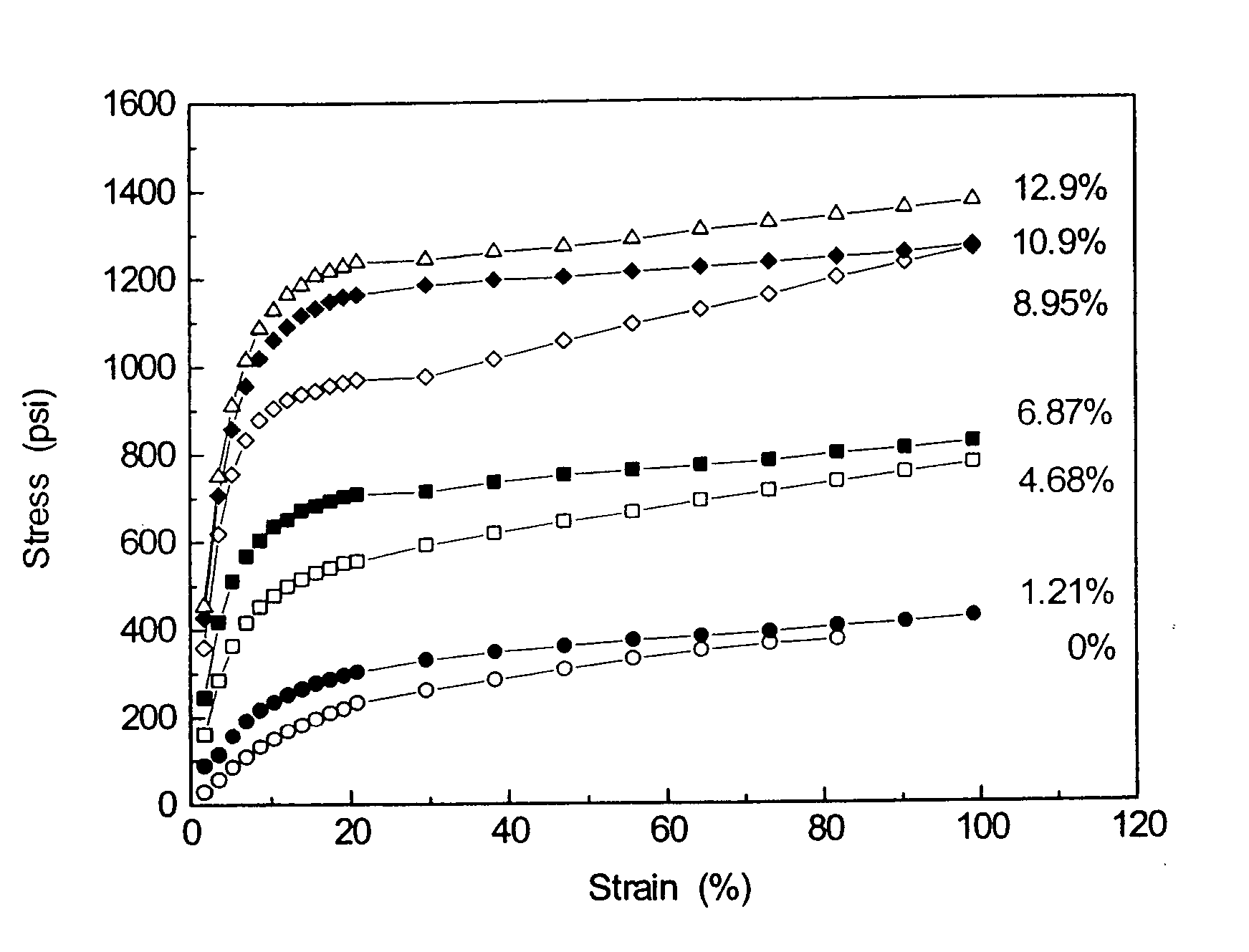
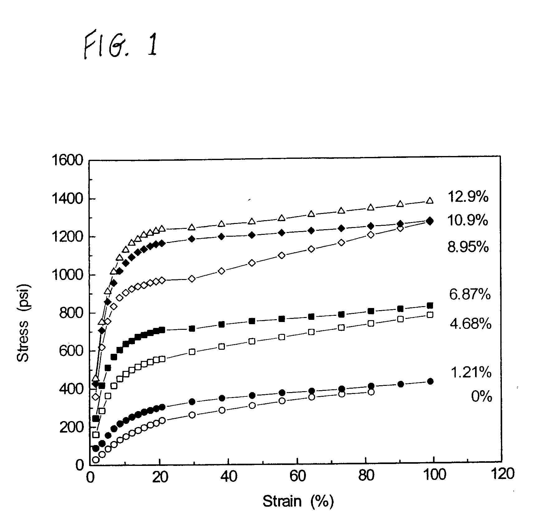
[0040] A nanocomposite material was prepared using various volume fractions (see FIG. 1) of vapor grown carbon nanofibers with a thermoplastic polyurethane polymer and tetrahydrofuran (THF). The solvent was removed by evaporation. FIG. 1 illustrates a stress-strain curve of the nanocomposite material as a function of the carbon nanofiber content. The curve illustrates that the tensile strength of the nanocomposite is increased from about 400 psi (no carbon nanofibers) to about 1400 psi when including 12.9% by volume of the carbon nanofibers.

example 2

[0041] A nanocomposite material was formed from polyurethane and carbon nanofibers in tetrahydrofuran (THF). The solvent was removed by evaporation. The abrasion resistance of the resulting nanocomposite was determined using a Plint friction test. A roller pin of 6mm×6 mm with a load of 550 g (5.4 Newton) was used for the test. The roller pin moved on the composite film with a stroke of 9 mm and a frequency of 2 Herz. The following Table 1 demonstrates that the film which contained no carbon nanofibers was torn in approximately 3 minutes, while the films which contained carbon nanofibers remained intact after 30 minutes of the test.

TABLE 1carbon nanotubesSample(wt %)Friction (N)CoefficientTime (min.)103.80.70˜3204.10.76>30316.63.60.67>30416.63.70.69>30528.82.30.43>30628.82.40.44>30

example 3

[0042] 6 grams of single-wall carbon nanotubes were obtained from Rice University and dispersed in a solvent comprising a mixture of 50% fuming sulfuric acid and 50% polyphosphoric acid in a Haake mixer at 180° C. for 30 minutes. 4 grams of a rigid-rod polymer poly(p-phenylene benzobisthiazole) was added to the mixture and mixed for one hour. The resulting solution mixture was transferred into an extrusion vessel and extruded into a fiber at 160° C. through a spinneret of 510 μm diameter. The fiber was coagulated in distilled water to remove the acids. After the fiber was thoroughly washed with watter, it was air dried. The dry fiber was also heat-treated under tension at 500° C. and 600° C., respectively. The fiber exhibited a diameter of 80 to 100 μm, a tensile strength of about 26 Kpsi, a Young's modulus of 1.8 Mpsi, and an electrical conductivity as high as 400 S / cm.


PUM

PropertyMeasurementUnit
Mechanical strengthaaaaaaaaaa
Dimensional stabilityaaaaaaaaaa
Thermoplasticityaaaaaaaaaa

Abstract

A method of reinforcing a polymeric material with nanosize materials is provided in which materials such as vapor grown carbon nanofibers, carbon nanotubes, layered silicates, nanosize sphered silica, or graphite nanoparticles are combined with a polymer and a solvent to form a substantially homogeneous mixture, followed by removal of the solvent by evaporation or coagulation. Depending on the nanosize materials used, the resulting polymeric nanocomposite material exhibits high electrical and thermal conductivity, enhanced mechanical strength, abrasion resistance, reduced gas permeation, and/or dimensional stability.

Description

CROSS REFERENCE TO RELATED APPLICATIONS [0001] This application is a continuation-in-part of U.S. patent application Ser. No. 10 / 698,218 filed Oct. 31, 2003, which application is a division of U.S. patent application Ser. No. 09 / 932,169 filed Aug. 17, 2001, now U.S. Pat. No. 6,680,016.BACKGROUND OF THE INVENTION [0002] The present invention is directed to a nanocomposite material incorporating uniformly dispersed nanosize materials, and to a method of forming such a nanocomposite material. [0003] It is known that nanosize materials such as vapor-grown carbon nanofibers or carbon nanotubes may be used to enhance the mechanical, electronic and thermal transport properties of polymers and other high-performance plastics for use in a variety of applications. For example, vapor-grown carbon nanofibers have been dispersed in polymer matrices by a polymer melt blending method in which the dispersants in the polymer matrix are mechanically sheared apart. See, for example, U.S. Pat. No. 5,64...

Claims


Application Information

Patent Timeline
IPC IPC(8): C08J3/205C08J5/00C08K7/24
CPCB82Y10/00B82Y30/00C08J3/205C08K2201/011C08J2375/04C08K7/24C08J5/005
Inventor WANG, CHYI-SHANALEXANDER, MAX D. JR.
Owner UNIV OF DAYTON
Why Eureka
Try Eureka