Optimized ultraviolet reflecting multi-layer coating for energy efficient lamps

Inactive Publication Date: 2005-06-16
GENERAL ELECTRIC CO
View PDF23 Cites 15 Cited by
  • Summary
  • Abstract
  • Description
  • Claims
  • Application Information

AI Technical Summary

Benefits of technology

[0014] One advantage of at least some embodiments of the present invention is to relieve a lamp arctube of the effects of hot spots, and to improve the spatial uniformity of the arctube temperature.
[0015

Problems solved by technology

Radiation emitted between 100-400 nm is ultraviolet (UV) radiation, which is harmful to human eyes and skin and which also causes fading, discoloration and degradation of fabrics, plastics, and paints.
In addition to the harmful effects of UV radiation which escapes a lamp, the UV radiation is essentially wasted, since it does not contribute to useful, visible illumination.
Newer metal halide products, however, such as fiber optic sources (see, for example, U.S. Pat. No. 4,958,263) and automotive lamps (see, for example, U.S. Pa

Method used


Image

  • Optimized ultraviolet reflecting multi-layer coating for energy efficient lamps
  • Optimized ultraviolet reflecting multi-layer coating for energy efficient lamps
  • Optimized ultraviolet reflecting multi-layer coating for energy efficient lamps

Examples


example 1

Off-Normal Optimization of UV Coatings

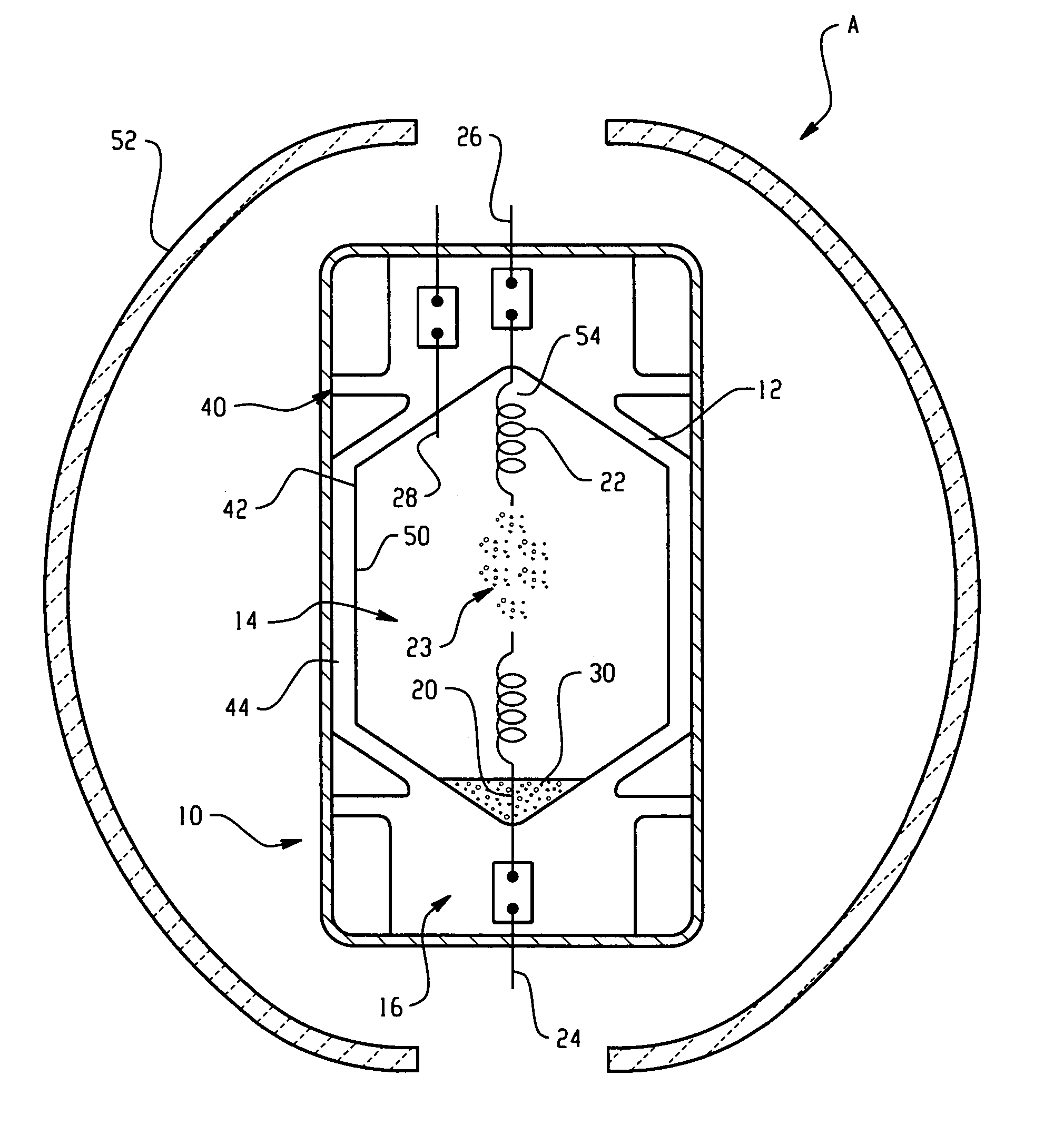
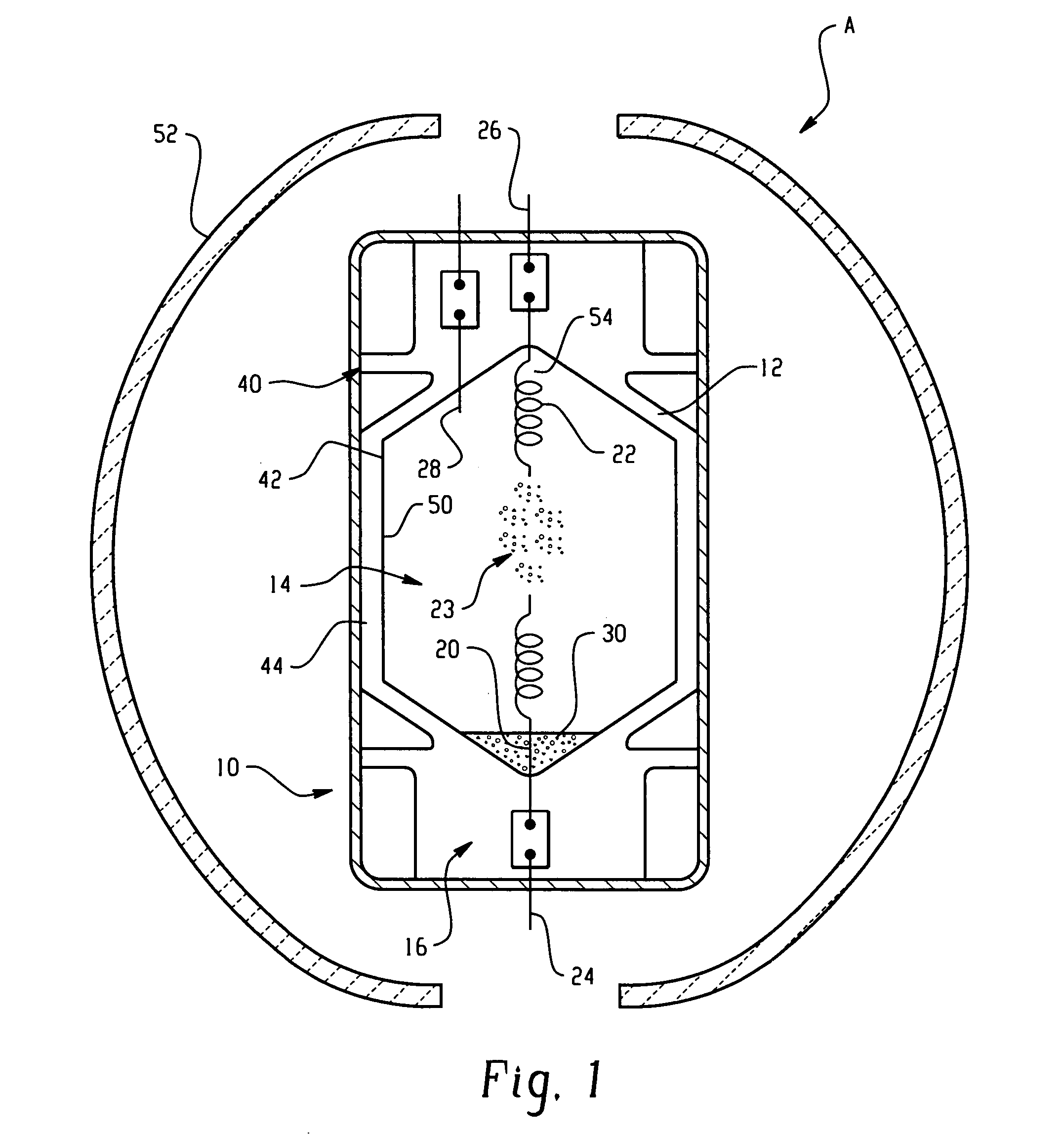
[0061] Multi-layer coatings optimized for 30 degree angle of incidence α were applied to vertically operated arctubes in HID metal halide lamps (GE's MVR400NBU). The arctubes were formed from undoped quartz and were substantially as shown in FIG. 1. The coatings were formed from alternating layers of Ta2O5 (high index material) and SiO2 (low index material) on a quartz substrate. The actual peak angle θP of the distribution of UV rays was determined with a ray tracing program to be about 26° and skewed toward higher angles, such that 30° is the preferred (mean) optimization angle α. In the case of the MVR400, two thirds of the distribution was found to fall between 0-45°.

[0062] The 30° optimized coating had a 96-98% reflectivity between about 300 and 365 nm and began to reduce around 370 nm.

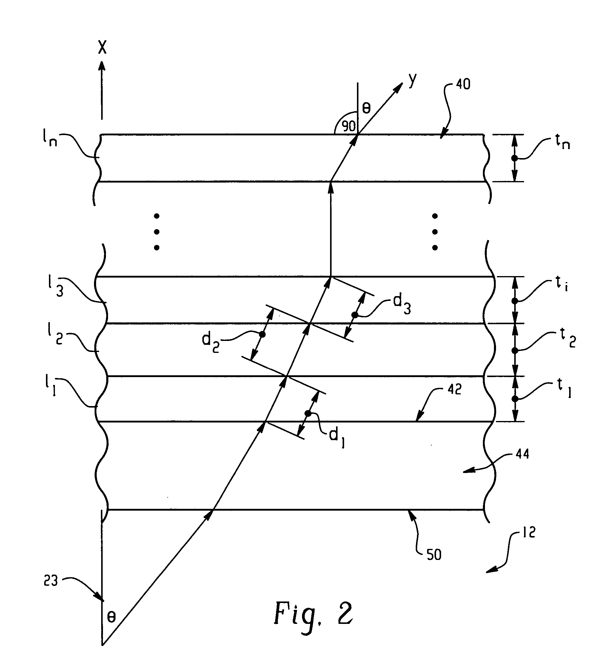
[0063] TABLE 2 lists the design of the 30° optimized coatings in terms of layer composition and thickness, starting with layer 1 (closest to the arctube ...

example 2

Calculated Improvement in Performance for 30° Optimized Lamps

[0066] The 30 degree optimized, high-reflectivity lamp of Example 1 was compared with other UV-coated lamps. TABLE 3 shows the results of ray tracing calculations of the amount of UV emitted by the arc which is delivered by the coating to the end of the arctube where the metal halide pool is located, as a function of reflectivity and optimization angle. The numbers shown in the table represent the percentage of rays emitted from the arc, in the wavelength range specified, which are ultimately reflected back to the metal halide pool. Thus, for example, in the near UV range (300-400 nm) only 30.8% of the UV rays emitted return to the metal halide pool for a low reflectivity (90%) coated tube optimized at 150 from normal, as compared to 49.9% for an equivalent arctube with a coating which is optimized at the optimization angle α=30° and formed for high reflectivity (averaging 98% in the 300-370 nm range). As can be apprecia...


PUM


Abstract

A metal halide lamp (10) includes a light-transmissive envelope (12) which encloses a metal halide pool (30) for generating a discharge when spaced apart electrodes (20, 22) within the envelope are supplied with an electric current. A multi-layer coating (40) is deposited on a surface (42) of the envelope. The coating includes several layers of at least two materials of different refractive index, which, in combination, reflect radiation in the UV region of the electromagnetic spectrum. Rather than optimizing the coating for a normal (i.e., 0°) angle of incidence on the coating, the multi-layer coating is optimized at an angle which is selected to be within 10° of the mean angle (α) of incidence of the UV radiation on the arctube surface, thereby increasing the amount of UV radiation which is returned to the metal halide pool. The coating is preferably optimized for high reflectivity in the UV-region of the spectrum and high transmission in the visible region of the spectrum to maximize useful light output while reflecting UV light back to the metal halide pool for improved heating of the pool.

Description

BACKGROUND OF THE INVENTION [0001] 1. Field of the Invention [0002] This invention relates to optical interference coatings for lamps and finds particular application in conjunction with a multi-layer ultraviolet (UV) reflecting coating for an arctube of a metal halide lamp which reflects UV radiation into the metal halide pool for increased efficiency of the lamp. [0003] 2. Discussion of the Art [0004] Metal halide lamps use a fill comprising a metal halide, mercury, and a rare gas. The metal halides, which often comprise sodium iodide and scandium iodide, are partially vaporized from the molten liquid pool during lamp operation. When the lamp is energized, an arc discharge is created, which emits radiation at wavelengths above about 200 nm. Radiation emitted between 100-400 nm is ultraviolet (UV) radiation, which is harmful to human eyes and skin and which also causes fading, discoloration and degradation of fabrics, plastics, and paints. In addition to the harmful effects of UV r...

Claims


Application Information

Patent Timeline
IPC IPC(8): H01J9/24H01J9/20H01J61/35
CPCH01J61/35
Inventor CHOWDHURY, ASHFAQUL I.ISRAEL, RAJASINGHALLEN, GARY R.
Owner GENERAL ELECTRIC CO
Why Eureka
Try Eureka