Laser thin film poly-silicon annealing system

Inactive Publication Date: 2005-06-30
CYMER INC
View PDF99 Cites 81 Cited by
  • Summary
  • Abstract
  • Description
  • Claims
  • Application Information

AI Technical Summary

Benefits of technology

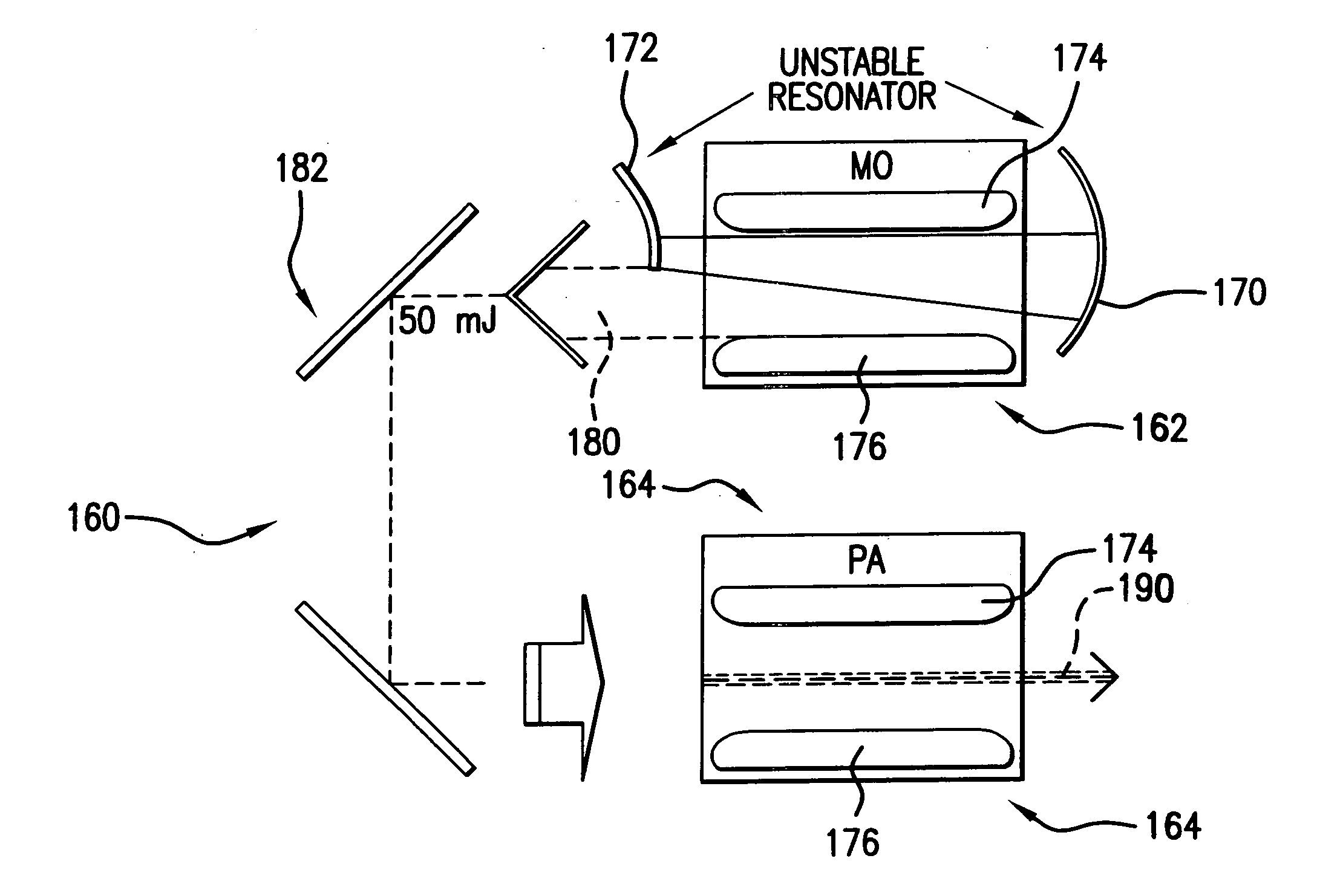
[0024] A gas discharge laser crystallization apparatus and method for performing a transformation of a crystal makeup or orientation in a film on a workpiece is disclosed, which may comprise a master oscillator power amplifier MOPA or power oscillator power amplifier configured XeF laser system producing a laser output light pulse beam at a high repetition rate and high power with a pulse to pulse dose control; an optical system producing an elongated thin pulsed working beam from the laser output light pulse beam. The apparatus may further comprise the laser system is configured as a POPA laser system and further comprising: relay optics operative to direct a first output laser light pulse beam from a first laser PO unit into a second las

Problems solved by technology

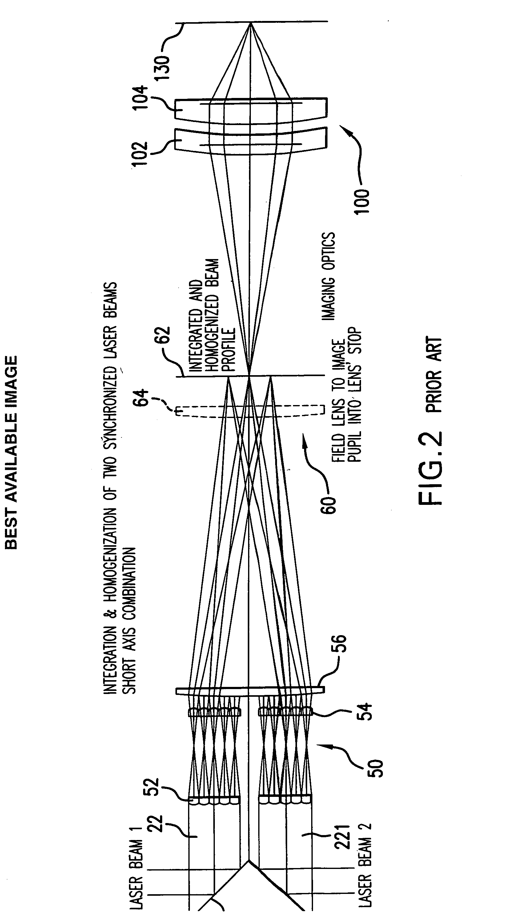
Voutsas also points out that in addition to the limitations of the projection optics, another source of beam-profile distortion is focusing.
For example, if, for a given projection lens, the location of the sample plane exceeds this limit in depth-of-focus, distortion in the imaged beam profile can occur, e.g., manifesting itself as “blurring;” i.e., the imaged beam cannot be fully resolved, with either underfocus and overfocus.
Voutsas also notes the variation of LGL as a function of the degree of defocusing in mm from the best focal plane, e.g., the lateral growth length being reduced with defocusing, due to the increased edge diffusion in the beam profile, which can render an increasing part of the beam ineffective for lateral growth.
Voutsas indicates that increasing the laser fluence can somewhat compensate f

Method used


Image

  • Laser thin film poly-silicon annealing system
  • Laser thin film poly-silicon annealing system
  • Laser thin film poly-silicon annealing system

Examples


Embodiment Construction

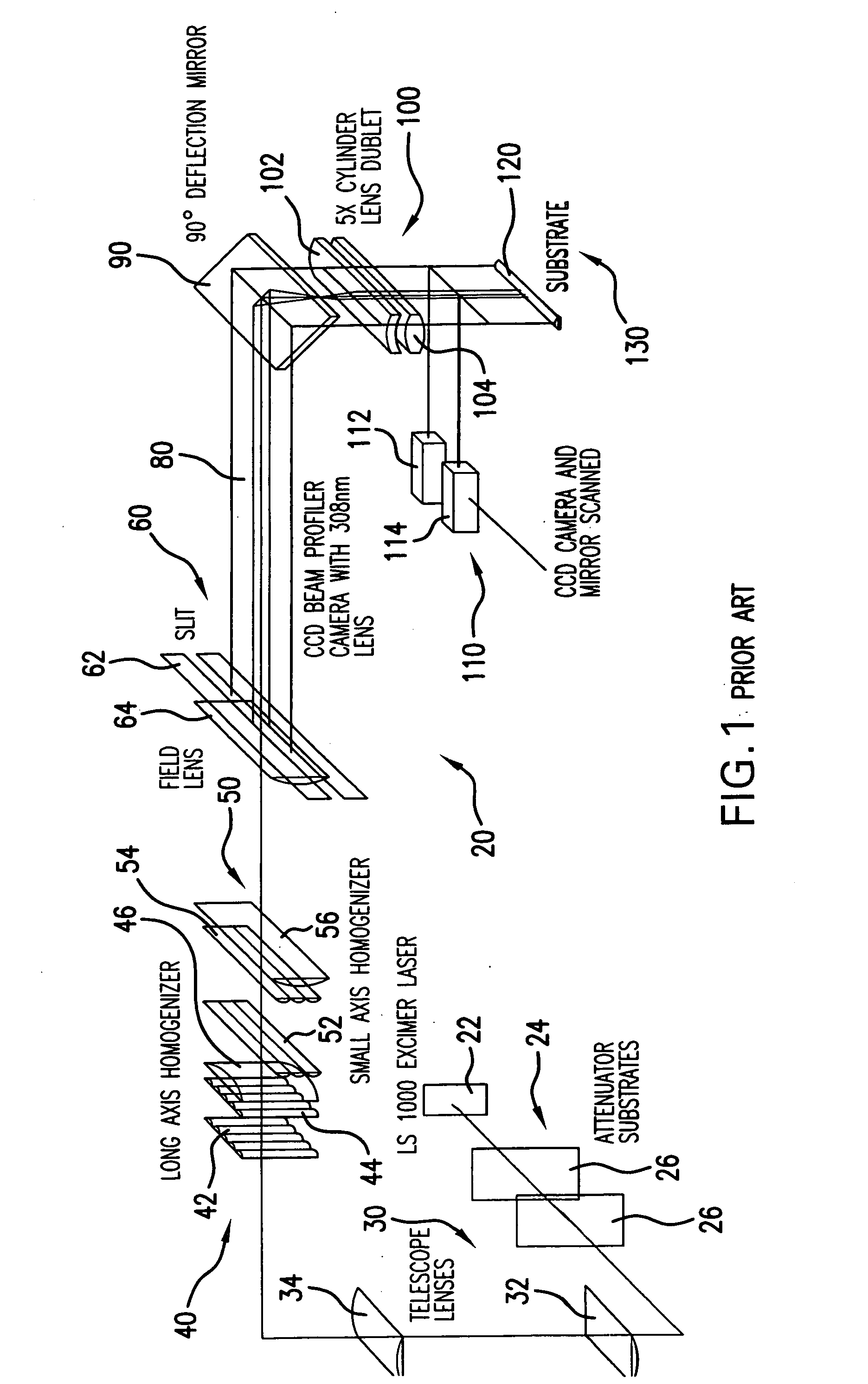
[0038] Applicants propose a directional SLS system that has simple optics for crystallization and activation, produces or can produce essentially grains that extend the length of the workpiece, yielding a mobility of 200-400 and a throughput of 35 sheets per hour. The maintenance per sheet form applicants' proposed system is about 37 percent cheaper than the JWS ELA system and has process margins that are insensitive to energy or focus in comparison to the JWS systems.

[0039] Applicants propose for a sheet size of 370×470 the capability of utilizing part of a beam that will cover the sheet comprising the substrate in one scan with a 365×0.02 mm or smaller elongated thin beam and will cover a 730×920 sheet with a single scan of an elongated thin beam of 730×0.02 mm with a laser repetition rate or at least 4000 Hz, overlap of, e.g., 90%, scan pitch of, e.g., 0.002 mm, scan length of 470 mm, enabling in the former case 235,000 crystallization shots per sheet, a 59 second crystallizatio...


PUM

PropertyMeasurementUnit
Timeaaaaaaaaaa
Poweraaaaaaaaaa

Abstract

A gas discharge laser crystallization apparatus and method for performing a transformation of a crystal makeup or orientation in a film on a workpiece is disclosed, which may comprise a master oscillator power amplifier MOPA or power oscillator power amplifier configured XeF laser system producing a laser output light pulse beam at a high repetition rate and high power with a pulse to pulse dose control; an optical system producing an elongated thin pulsed working beam from the laser output light pulse beam. The apparatus may further comprise the laser system is configured as a POPA laser system and further comprising: relay optics operative to direct a first output laser light pulse beam from a first laser PO unit into a second laser PA unit; and, a timing and control module timing the creation of a gas discharge in the first and second laser units within plus or minus 3 ns, to produce the a second laser output light pulse beam as an amplification of the first laser output light pulse beam. The system may comprise divergence control in the oscillator laser unit. Divergence control may comprise an unstable resonator arrangement. The system may further comprise a beam pointing control mechanism intermediate the laser and the workpiece and a beam position control mechanism intermediate the laser and the workpiece. Beam parameter metrology may provide active feedback control to the beam pointing mechanism and active feedback control to the beam position control mechanism.

Description

RELATED APPLICATIONS [0001] This application is a continuation-in-part of U.S. application Ser. No. 10 / 781,251, entitled VERY HIGH ENERGY, HIGH STABILITY GAS DISCHARGE LASER SURFACE TREATMENT SYSTEM, filed on Feb. 18, 2004, Attorney Docket No. 2003-0105-02, which was a continuation-in-part of Ser. No. 10 / 722,992, entitled VERY HIGH ENERGY, HIGH STABILITY GAS DISCHARGE LASER SURFACE TREATMENT SYSTEM, filed on Nov. 26, 2003, which was a continuation in part of U.S. patent application, Ser. No. 10 / 722,992, entitled Ser. No. 10 / 631,349, entitled CONTROL SYSTEM FOR TWO CHAMBER GAS DISCHARGE LASER, filed Jul. 30, 2003; and which was a continuation-in-part of Ser. No. 10 / 233,253, entitled LITHOGRAPHY LASER WITH BEAM DELIVERY AND BEAM POINTING CONTROL, filed on Aug. 30, 2002; which was a continuation-in-part of Ser. No. 10 / 012,002, now U.S. Pat. No. 6,625,191, filed on Nov. 30, 2001, entitled VERY NARROW BAND, TWO CHAMBER, HIGH REP RATE GAS DISCHARGE LASER SYSTEM, issued on Sep. 23, 2003, a...

Claims


Application Information

Patent Timeline
IPC IPC(8): B23K26/06G03FH01L21/20H01S3/081H01S3/22H01S3/223H01S3/225H01S3/23
CPCB23K26/041B23K26/063B23K26/0738B23K26/426H01L21/02532H01S3/2366H01S3/0818H01S3/225H01S3/2255H01S3/2308H01L21/02675B23K26/0622B23K26/042B23K26/705
Inventor PARTLO, WILLIAM N.DAS, PALASH P.HUDYMA, RUSSELLTHOMAS, MICHAEL
Owner CYMER INC
Why Eureka
Try Eureka