Method and system for hardware accelerated verification of digital circuit design and its testbench

a hardware acceleration and digital circuit technology, applied in the field of hardware acceleration verification of hardware circuit design, can solve the problems of simulators typically not achieving a speed of not more than a few tens to hundreds of clock cycles per second (cps), and synthesis tools presently cannot be used to synthesize behavioral test benches, etc., to achieve the effect of fast verification of design

Active Publication Date: 2005-06-30
SIEMENS PROD LIFECYCLE MANAGEMENT SOFTWARE INC
View PDF2 Cites 47 Cited by
  • Summary
  • Abstract
  • Description
  • Claims
  • Application Information

AI Technical Summary

Benefits of technology

[0010] Aspects of the present invention may overcome one or more of the drawbacks of the prior art by synthesizing the DUT itself and the test environment (i.e., the test

Problems solved by technology

However, synthesis tools presently do not attempt to maintain the identical behavior in actual circuitry as defined in the behavioral model.
Therefore, such synthesis tools can not be used for synthesizing behavioral testbenches.
However, simulators have a disadvantage in that, for large designs, simulators typically can achieve a speed of not more

Method used


Image

  • Method and system for hardware accelerated verification of digital circuit design and its testbench
  • Method and system for hardware accelerated verification of digital circuit design and its testbench
  • Method and system for hardware accelerated verification of digital circuit design and its testbench

Examples


case 1

[0090] two synchronous processes using different clocks. This case may be resolved using the multi-clock macro discussed above.

case 2

[0091] two synchronous processes using same clock. As discussed earlier, such cases are un-ambiguous only if the assignments don't occur at the same simulation time. Thus, a special circuit may be used that produces correct results when the assignments are mutually exclusive in time. To explain the circuit, every process assumes that it is the only driver for a register and sends out the next cycle value for that register to a flip flop. In case there are two such processes, two next cycle values are being sent to this circuit. The circuit chooses the value that is different from the current value of the register. This works because if the next value is different from the current one it has to be due to an assignment from that process. FIG. 8B illustrates this arrangement.

case 3

[0092] two non-RTL processes. Recall that non-RTL processes are nothing but RTL processes synchronous with the behavioral clock. Thus, the solution applied to CASE 2 works in this case as well.

Zero Delay Cycles

[0093] In Verilog, special meaning has been assigned to the #0 statement (i.e., a zero delay cycles statement). Assignments that are scheduled non-blockingly cannot mature at #0. Thus, a #0 statement is a special zero delay cycle, which is similar to blocking zero delay cycles.

[0094] During a #0, the global minimum time advance may take a zero value. For this reason, a non-blocking maturity global signal also depends on the global minimum being non-zero to assert itself, thus ensuring that non-blocking zero delay cycles are deferred when #0 is being executed.

System Tasks / Functions

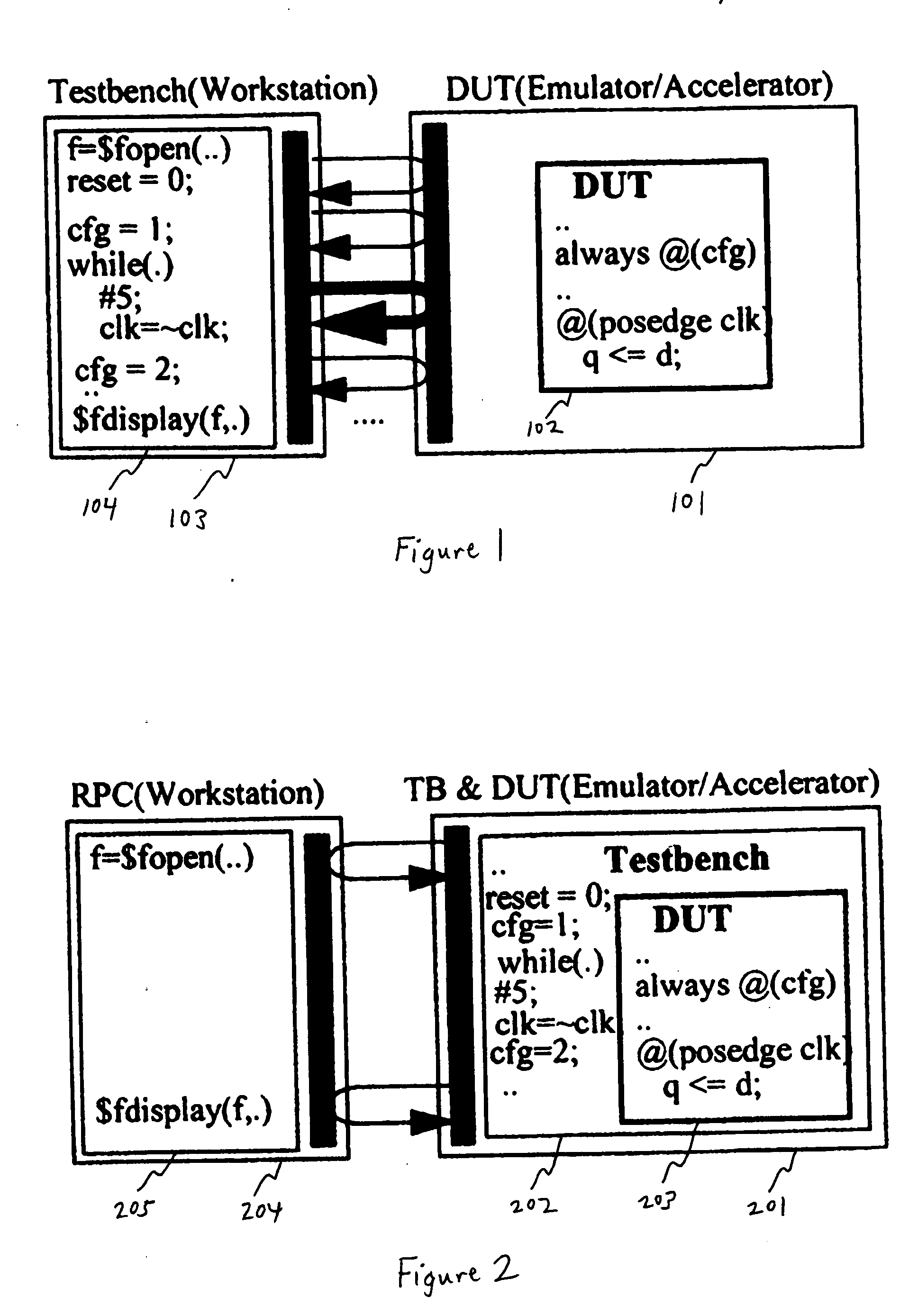
[0095] As mentioned earlier, system tasks / functions are implemented as remote procedural calls. The actual execution of these tasks may take place in the workstation 204. The procedural blocks ...


PUM


Abstract

A system and method is presented for synthesizing both a design under test (DUT) and its test environment (i.e., the testbench for the DUT), into an equivalent structural model suitable for execution on a reconfigurable hardware platform. This may be achieved without any change in the existing verification methodology. Behavioral HDL may be translated into a form that can be executed on a reconfigurable hardware platform. A set of compilation transforms are provided that convert behavioral constructs into RTL constructs that can be directly mapped onto an emulator. Such transforms are provided by introducing the concepts of a behavioral clock and a time advance finite state machine (FSM) that determines simulation time and sequences concurrent computing blocks in the DUT and the testbench.

Description

FIELD OF THE INVENTION [0001] The present invention relates to the field of verification tools for hardware circuit design. More specifically, the invention relates to the field of synthesis for hardware-assisted verification. BACKGROUND OF THE INVENTION [0002] Hardware Description Languages (HDLs) are predominantly used to describe integrated circuit designs. Various HDLs exist in the market today such as Very High Speed Integrated Circuit HDL (VHDL), Verilog, and System Verilog. HDL may be used to describe a design at various levels of abstraction. For instance, VHDL supports many possible levels / styles of design description. These styles differ primarily in how closely they relate to the underlying hardware. Some levels focus more on the behavior and dataflow of a design, while other levels focus more on the structural and timing aspects of the design. [0003] For example, integrated circuit designs may be described at the dataflow level of abstraction, often called the register t...

Claims


Application Information

Patent Timeline
IPC IPC(8): G01R31/3183G06F17/50
CPCG06F17/5027G01R31/318314G06F30/331
Inventor DAW, JYOTIRMOYGUPTA, SANJAYKRISHNAMURTHY, SURESH
Owner SIEMENS PROD LIFECYCLE MANAGEMENT SOFTWARE INC
Why Eureka
Try Eureka