Data transfer system and method, data transmitter, data receiver, data transmission method, and data reception method

a data transmission and data technology, applied in the field of data transmission system and method, a data transmitter, a data receiver, a data transmission method, and a data reception method, can solve the problems of data not being freely transmitted at the desired time, multipolar cables and connectors cannot be used, serial-to-parallax conversion timing cannot be accurately obtained in the data transmitter, etc., to achieve simplified structure of the transmitter and the receiver

Active Publication Date: 2005-07-07
SONY CORP
View PDF13 Cites 71 Cited by
  • Summary
  • Abstract
  • Description
  • Claims
  • Application Information

AI Technical Summary

Benefits of technology

[0024] Regarding a word clock combined with data into a multi-level logic signal, the word clock indicates a word delimiter of serial data obtained by parallel-to-serial conversion. Therefore, it is unnecessary to perform complicated processing, e.g., temporarily interrupt data transfer and transmit a special signal indicative of the head of a word. Advant

Problems solved by technology

In many cases, however, multipolar cables and connectors cannot be used because transmission distance or mounting area and volume are limited.
According to the principle of LVDS, disadvantageously, even if data multiplexing is improved, at least two transmission lines are inevitably required to transmit data and a clock.
Further, if the difference in time between the two transmission lines, namely, skew occurs, the timing of serial-to-parallel conversion in the data transmitter cannot be accurately obtained.
Disadvantageously, data cannot be freely trans

Method used


Image

  • Data transfer system and method, data transmitter, data receiver, data transmission method, and data reception method
  • Data transfer system and method, data transmitter, data receiver, data transmission method, and data reception method
  • Data transfer system and method, data transmitter, data receiver, data transmission method, and data reception method

Examples


first embodiment

[0043] A data transfer system according to a first embodiment of the present invention will now be described in detail with reference to the drawings.

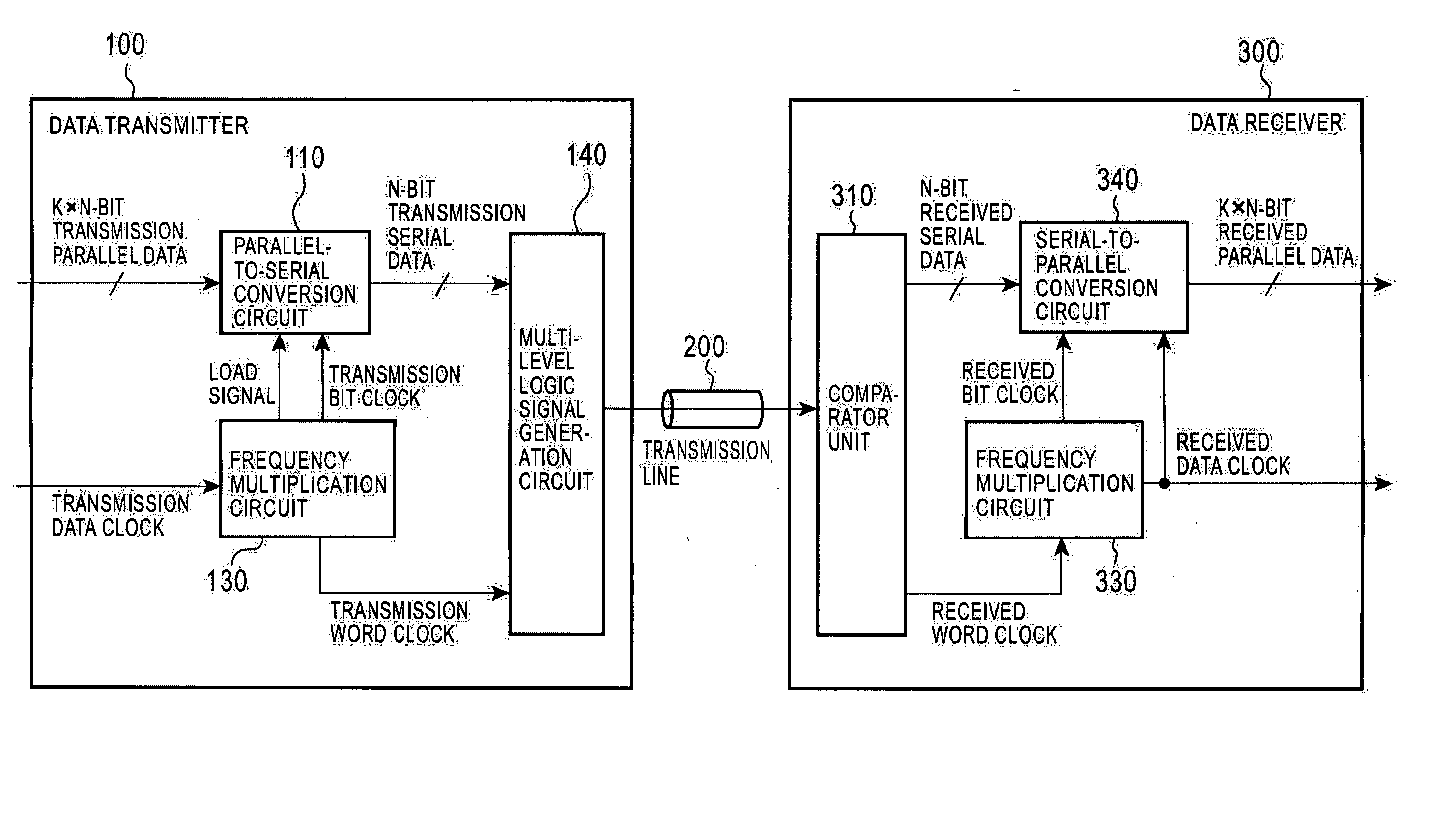
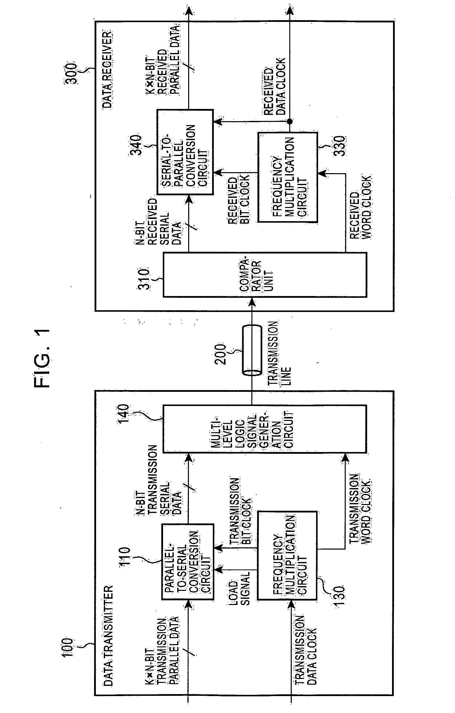
[0044]FIG. 1 is a block diagram of the data transfer system according to the first embodiment of the present invention.

[0045] According to the first embodiment, the data transfer system includes a data transmitter 100 and a data receiver 300. The data transmitter 100 converts multi-bit transmission parallel data to be transferred into transmission serial data, combines a transmission word clock, indicating a word delimiter of the transmission serial data, as one-bit information with the transmission serial data to generate a multi-level logic signal representing a plurality of bits of information in one symbol, and then transmits the multi-level logic signal to a transmission line 200. The data receiver 300 receives the multi-level logic signal through the transmission line 200, extracts received serial data that is the same as the t...

second embodiment

[0108] A data transfer system according to a second embodiment of the present invention will now be described.

[0109] In high speed wire communication, voltage swing which can be used as a transmission signal is up to several hundreds of mV at the maximum in terms of electromagnetic interference (EMI) and power consumption. For a multi-level signal using divided voltage swing segments, disadvantageously, noise margin is reduced. In order to accomplish transmission with a small noise margin and no errors, high external noise immunity and precise impedance matching between a transmission line and a termination resistor causing no reflection are of importance. Further, it is important to identify received data at the optimum timing at which the maximum noise margin can be obtained.

[0110] The data transfer system according to the second embodiment of the present invention is made in consideration of the above problems.

[0111]FIG. 10 is a block diagram of the data transfer system accord...

third embodiment

[0140] A data transfer system according to a third embodiment of the present invention will now be described below. The present system is suitable for a case where its transmission line includes AC coupling.

[0141] According to the above-mentioned first and second embodiments, an average DC value of a multi-level logic signal when all of transmission parallel data indicate “0” differs from that when all of the transmission parallel data indicate “1”. In AC-coupled transmission through which the DC component of a signal does not pass, a data receiver cannot identify the value of a multi-level logic signal because the DC component of the signal is lost, resulting in inaccurate signal reproduction.

[0142]FIG. 16 is a block diagram of the data transfer system according to the third embodiment of the present invention.

[0143] In the data transfer system according to the third embodiment, a data transmitter 400a includes an 8B10B encoder 440 for converting eight-bit transmission parallel ...


PUM


Abstract

The present invention provides a data transfer system including a data transmitter and a data receiver. The data transmitter converts a plurality of bits of transmission parallel data into serial data and generates a multi-level logic signal representing a plurality of bits of information in one symbol, the information being obtained by combining the serial data with a word clock as one-bit information. The word clock indicates a word delimiter in the serial data. The data receiver receives the transmitted multi-level logic signal, extracts the serial data and the word clock from the signal, and reproduces the parallel data based on the extracted word clock. In the data transfer system, a multi-bit digital signal can be transmitted as one signal including a word clock. Thus, components and mounting space to be allocated to transfer can be reduced.

Description

BACKGROUND OF THE INVENTION [0001] 1. Field of the Invention [0002] The present invention relates a data transfer system and method, a data transmitter, a data receiver, a data transmission method, and a data reception method and, more particularly, to a data transfer system and method for multi-bit digital data transfer, a data transmitter, a data receiver, a data transmission method, and a data reception method for the same. [0003] 2. Description of the Related Art [0004] Many industrial applications require multi-bit digital data transfer. In many cases, however, multipolar cables and connectors cannot be used because transmission distance or mounting area and volume are limited. Then, various multiplexing approaches are used. [0005] As a typical example of conventional digital data transfer, digital data transfer to a high-definition color liquid crystal monitor of a computer or the like will now be described. [0006] Digital Interface Standards for Monitor as JEIDA standards (ht...

Claims


Application Information

Patent Timeline
IPC IPC(8): H03K19/20H03M9/00H04B3/36H04L7/00H04L7/033H04L25/49
CPCH03M5/20H04L25/4917H04L7/033H03M9/00H04L7/00
Inventor KIKUCHI, HIDEKAZU
Owner SONY CORP
Why Eureka
Try Eureka