
Apparatus and methods usable in connection with dispensing flexible sheet material from a roll

Inactive Publication Date: 2005-07-14
GPCP IP HLDG LLC
View PDF99 Cites 64 Cited by
  • Summary
  • Abstract
  • Description
  • Claims
  • Application Information

AI Technical Summary

Benefits of technology

[0023] The present inventions arose out of efforts to develop a “next generation” sheet material dispenser providing increased convenience and simplicity of use and maintenance. In particular, it was an object of the inventors to provide a dispenser capable of carrying out dispensing operations in a reliable and controlled manner that would avoid the need for a user to make physical contact with the dispenser. The inventors also sought to develop a dispenser that would, by virtue of its various features, minimize dispenser downtime due to depletion of the dispensed roll material or the dispenser power supply, or due to jams of the feed mechanism. Moreover, the inventors sought to develop a dispenser that would improve the efficiency of institutional / building maintenance operations, by facilitating dispenser maintenance by unskilled personnel.
[0030] According to a fourth one of the inventions, a dispenser for dispensing flexible sheet material includes a feed mechanism, a drive mechanism for selectively driving the feed mechanism, and a control device for controlling the drive mechanism. A battery container is provided for removably holding at least one battery for powering at least one of the drive mechanism and the control device. A power line input port is provided, to which a power line may be connected to supply power to at least one of the drive mechanism and the control device in lieu of battery power. The power line input port is arranged in relation to the battery container such that (1) when the battery container is loaded with the at least one battery to supply power to at least one of the drive mechanism and the control device, the line input port is prevented from being connected to the power line; and (2) when the battery container is unloaded, the power line input port is readily accessible for connection of the power line.
[0041] In a thirteenth one of the present inventions, a method is provided for providing substantially constant sensitivity for sensing changes in a baseline stray capacitance to an antenna. According to this invention, an oscillation signal is generated by an oscillator circuit, preferably having a Colpitts oscillator-type topography, and coupled to the antenna. The oscillation signal has a predetermined oscillation amplitude corresponding to the baseline stray capacitance of the antenna. The oscillation amplitude of the oscillation signal increase in response to an increase in stray capacitance from the baseline stray capacitance of the antenna and decreases in response to a decrease in stray capacitance from the baseline stray capacitance of the antenna. A change in the oscillation amplitude of the oscillator signal is preferably detected and the amplitude of the oscillator signal is preferably controlled by controlling a current in the oscillator circuit to counteract the detected change in stray capacitance from the baseline stray capacitance of the antenna. The oscillation amplitude of the oscillator signal is maintained at the predetermined oscillation amplitude to provide a substantially constant sensitivity to changes in stray capacitance from the baseline stray capacitance of the antenna. A detect signal is preferably generated when an increase in the oscillation amplitude is detected, such as when a hand is placed in proximity to the antenna. The oscillator circuit may include a shield that is driven with a signal related to the oscillation signal, thereby reducing the baseline stray capacitance of the antenna by an amount that may be about two orders of magnitude greater than an increase in stray capacitance that generates the detect signal.

Problems solved by technology

Although economical, the continuous exposure of the soiled toweling is deemed unsightly and, therefore, unacceptable to many consumers when compared to the many available alternatives.
Further, the exposure and possible reuse of soiled toweling may present additional health hazards and sanitation concerns which should be avoided.
However, a number of the folded towels will sometimes drop out of the lower opening of the dispenser when only the exposed towel is pulled, especially when the stack of towels in the dispenser is small.
This can result in a significant waste of paper towels.
Accordingly, folded towels are not as economical as other kinds of alternative dispensers.
However, as can be appreciated, manual contact with a dispensing lever or the like raises health concerns for the user.
Paper possessing the requisite strength to operate the dispenser is limited in the amount of softness and absorbency which can be provided to the paper towels.
While the feed roller is powered, the cutting action still requires the paper to possess a certain minimum strength and generally produces a rough, unsightly cut.
While this arrangement enables the use of softer and more absorbent paper, the dispenser requires a substantial amount of energy to drive the feed mechanism and the reciprocating cutter.
Moreover, the system is more complex and costly with its use of one-way clutches.
Hence, the dispenser is subject to easy abuse and waste of paper.
However, the need to wait can be frustrating to users under some circumstances.
While the Goodin et al. sensing system purports to provide high reliability in avoiding false sensing situations, it is apparent that the stray capacitance provided by the environment in which a Goodin et al. sensor is installed may adversely affect the frequency of oscillation of the oscillator such that the oscillator circuit must be calibrated so that the sensitivity of the theremin sensor can reliably sense the change in capacitance provided by a person's hand.
This can require complex towel threading and loading sequences.
In contrast to folded paper towel dispensers, conventional roll towel dispensers do not provide an economical way to replenish the towel supply when a partially depleted roll, i.e., a “stub” roll, remains within the dispenser.
In some prior art dispensers, a new roll must be substituted for the stub roll, thereby resulting in the waste of whatever paper remains on the stub roll.
This can result in increased operational costs as a significant amount of paper may be wasted in facilities with many dispensers.
Unfortunately, tension responsive transfers are not particularly reliable since conditions other than reaching the end of the roll can trigger their operation, such as the slackening of the web or a break in the web material.
Diameter responsive transfers also have a drawback in that the reserve web begins dispensing prior to the complete exhaustion of the primary roll.
Thus, for a short time web material is dispensed simultaneously from both rolls and again results in a waste of material.
The use of sensing fingers on the web material, however, produces extra friction which can inadvertently tear the web.
Moreover, the introduction of additional components to sense the absence of the web and transfer the reserve web to between the feed rollers creates opportunities for a transfer failure to occur.
While generally quite effective, the movement and spring biasing of a relatively high mass feed roller can lead to difficulties.
If the spring bias is set too high, the biasing force may inhibit smooth feeding of the web material through the rollers, and result in tearing of the web material.
If it is set too low, the mechanism may not actuate effectively to cause a transfer of feed to the reserve roll immediately upon depletion of the stub roll.
Over time, the spring bias provided to move one roll relative to the other is prone to eventually decrease, e.g., due to fatigue of the spring, such that ultimately the spring force may fall below the required relatively narrow range and thus be insufficient to properly actuate a web transfer.

Method used


Image

  • Apparatus and methods usable in connection with dispensing flexible sheet material from a roll
  • Apparatus and methods usable in connection with dispensing flexible sheet material from a roll
  • Apparatus and methods usable in connection with dispensing flexible sheet material from a roll

Examples


Embodiment Construction

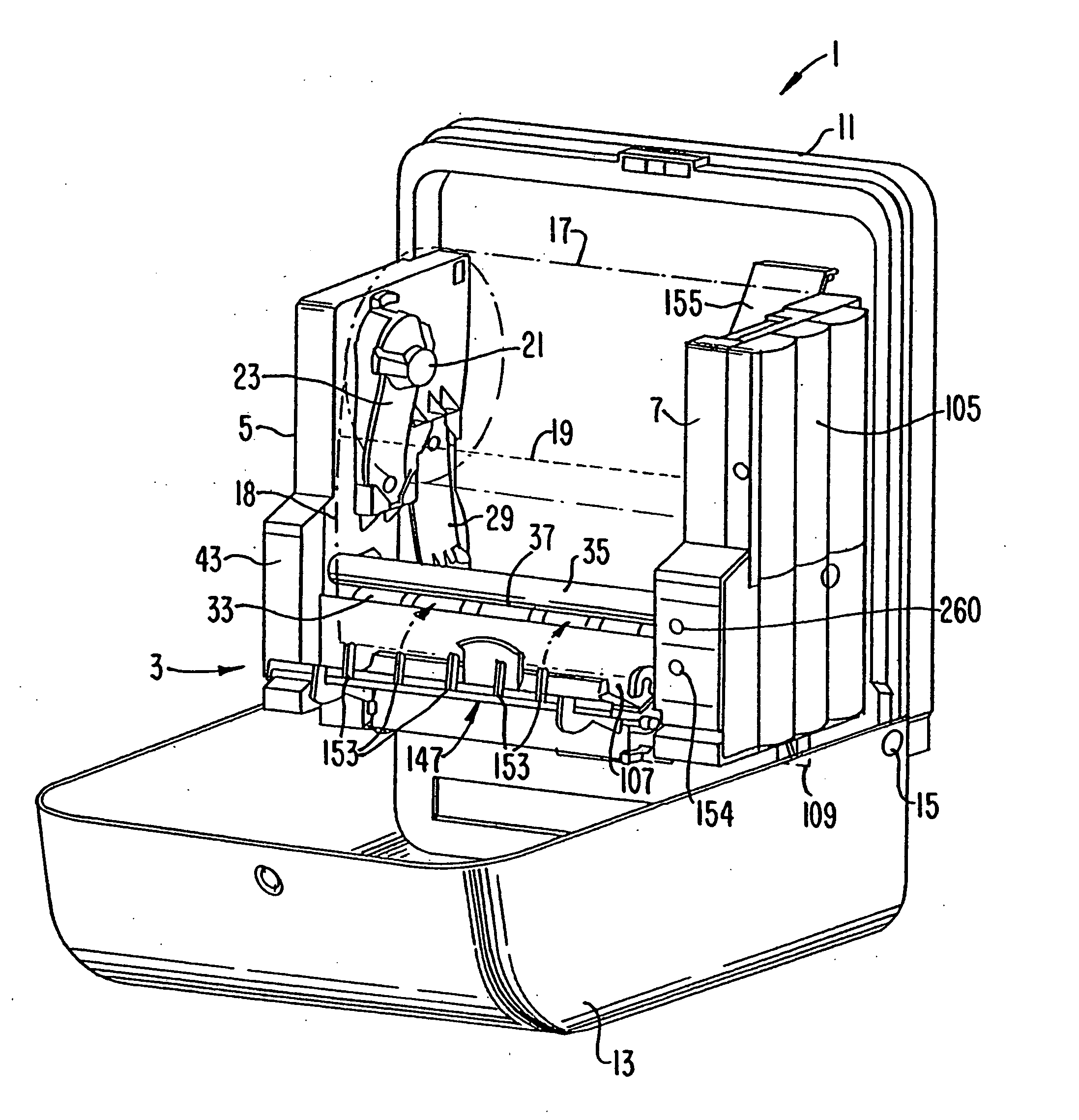
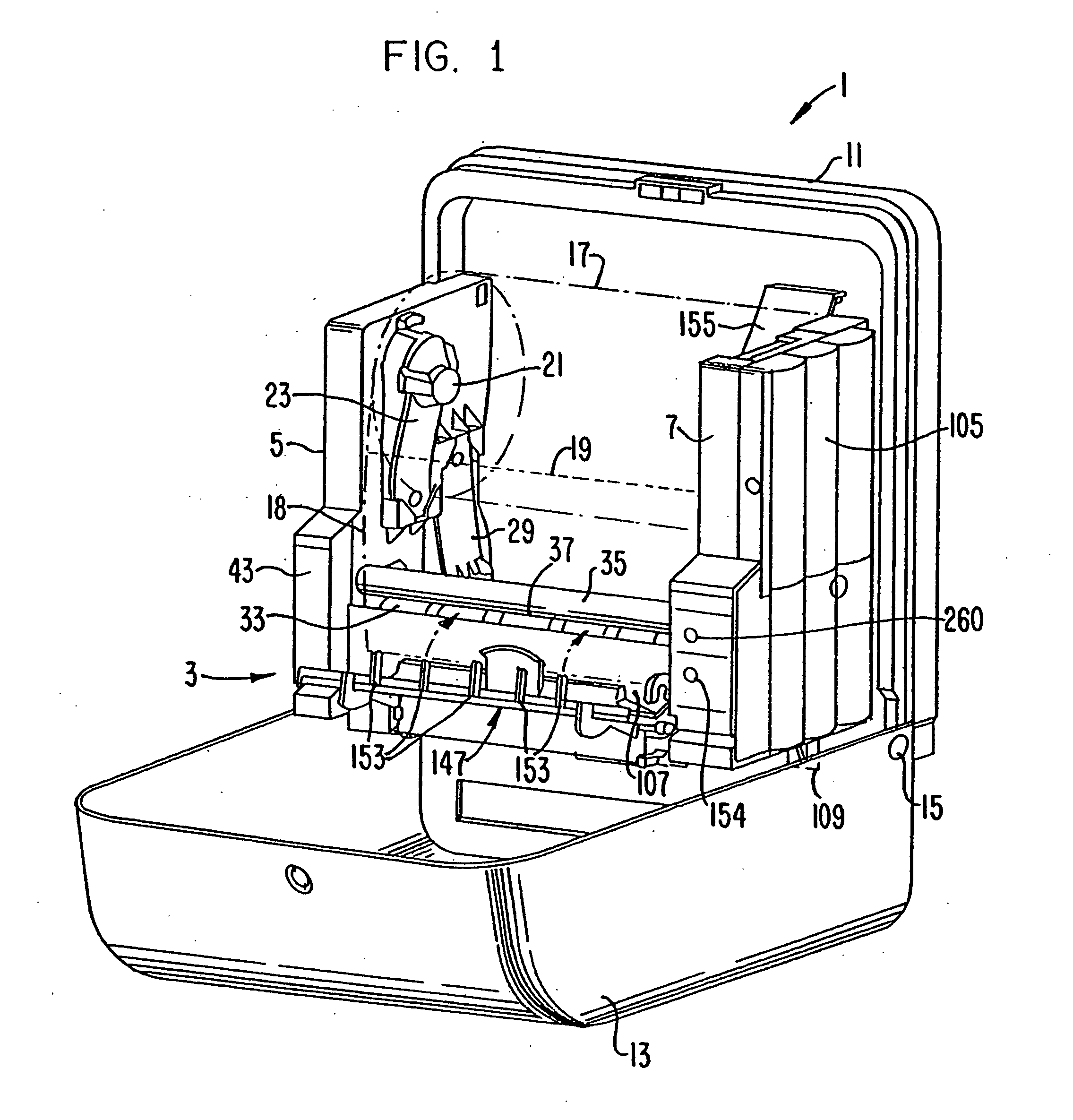
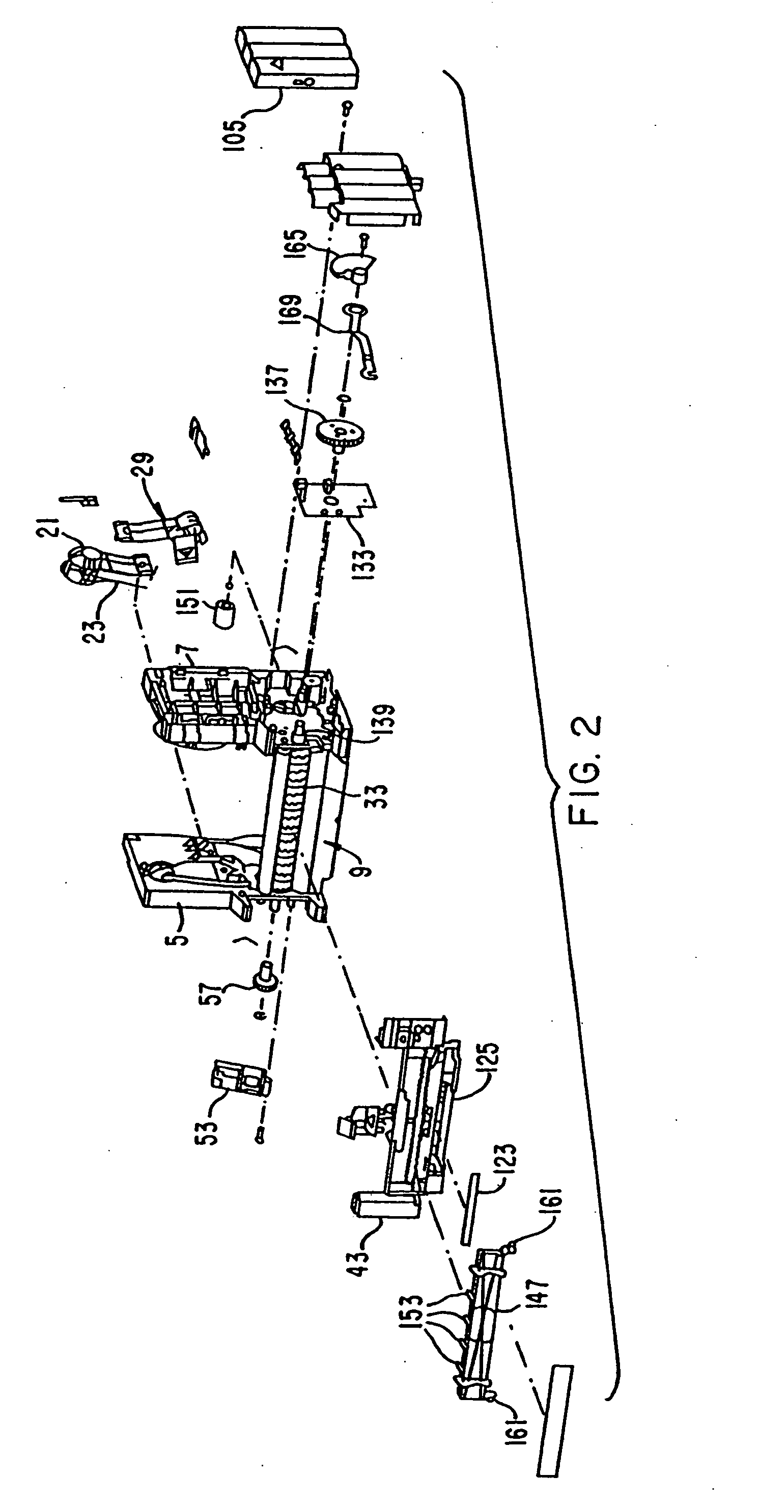
[0067] Referring first to FIGS. 1-3, a paper towel dispenser I according to the present invention comprises a chassis assembly 3 that includes a right side chassis member 5, a left side chassis member 7, and a middle chassis member 9 extending between the side chassis members. Dispenser 1 further includes a back panel member 11 and a pivotal front cover 13 attached, by a pin 15, hinge or other convenient attachment mechanism, to back panel member 11. Front cover 13 may be opened and pivoted away from chassis assembly 3 to a web loading position (as shown) allowing a roll 17 of a web material 18 to be loaded into dispenser 1.

[0068] In the illustrated exemplary embodiment, roll 17 comprises a continuous web 18 of flat segments of paper towel material wound upon a hollow cylindrical core. Dispenser 1 could, of course, dispense other flexible webs, paper or otherwise. The web could, e.g., be in the form of folded sheet segments wound onto a roll and separable from each other along line...


PUM


Abstract

A powered dispenser for dispensing individual sheet segments from a continuous roll of sheet material provided with spaced tear lines comprises a powered feed mechanism, a releasable, powered drive mechanism, a powered transfer mechanism, a pair of web sensing sensors, a capacitive sensing system providing automatic sensitivity adjustment, and control circuitry. A dual power supply system provides a mechanical lock-out functionality, and the control system is protected from electrostatic build-up on the surface of the feed roller. The web sensor, and an antenna plate of the capacitive sensing system, are provided on respective printed circuit boards mounted in overlying relation. Utilizing signals received from the pair of web sensors and the capacitive sensing system, the control circuitry senses the presence of a user to activate the powered drive mechanism, and prevents further dispensing of the sheet material until a previously dispensed segment is separated from the roll. The web sensors detection of a leading edge of the sheet material initiates a predetermined interval of sheet material advancement providing a proper placement of successive tear lines. Various approaches may be utilized to accommodate inadvertent sheet “tabbing” scenarios. The web sensors, together with the control circuitry, are also used to detect the depletion, or absence, of a working roll of sheet material, whereupon the control circuitry controls the powered transfer mechanism to automatically transfer the web feed supply from a depleted working roll to a reserve roll. The powered transfer mechanism may include a motor driven transfer bar, or provide motor driven release of a spring biased transfer bar. Another arrangement allows for ready release of a roll core, and drop of the same into an open dispenser cover for removal.

Description

[0001] This application is a divisional of U.S. application Ser. No. 10 / 211,334, filed Aug. 5, 2002, which is a divisional of U.S. application Ser. No. 10 / 092,350, filed on Mar. 7, 2002.FIELD OF THE INVENTIONS [0002] The present inventions relate to the dispensing of flexible sheet material from a roll. In particular, the present inventions relate to various features that may be advantageously used by themselves or in conjunction with each other, in connection with the dispensing of web products (e.g., paper towels or napkins) from a roll in an institutional setting. A proximity sensing circuit and method in accordance with one invention may be advantageously applied in virtually any application where it is desired to detect the presence or proximity of a user or object relative to something else. The inventions described herein compliment each other as well as: the powered dispensing and user sensing related inventions disclosed in co-pending commonly owned patent application Ser. ...

Claims


Application Information

Patent Timeline
IPC IPC(8): A47K10/36B65H35/10
CPCA47K10/36H03K2017/9606B65H35/10A47K2010/3668A47K2010/3881A47K10/3612A47K10/3625Y10T83/8822Y10T83/541Y10T225/268Y10T225/205Y10T83/889Y10T225/232Y10T225/238Y10T225/30Y10T225/12Y10T83/896Y10T225/209
Inventor MORRIS, ANDREW R.BOONE, BRUCE T.SUSI, MICHAEL A.DOWD, PAULISAKSSON, WILL
Owner GPCP IP HLDG LLC
Learn More