Assembly and method for wavelength calibration in an echelle spectrometer

Active Publication Date: 2005-07-21
LEIBNIZ - INSTITUT FUER ANALYTISCHE WISSENSCHAFTEN ISAS +1
View PDF7 Cites 12 Cited by
  • Summary
  • Abstract
  • Description
  • Claims
  • Application Information

AI Technical Summary

Benefits of technology

[0018] In a particularity preferred embodiment of the invention the means for the wavelength calibration of the echelle spectrometer comprise a light source with a line spectrum, emitting light which can be imaged on the intermediate slit and means are provided for adjusting a line detected with the detector in a reference position. This kind of calibration enables a wavelength adjustment in such a way that the remaining error is determined by the measuring error of the detector only and not by the error of the mechanical adjustment of the rotation of the grating. The line spectrum of the calibration light source can occur in a wavelength range which is at a large distance from the wavelength to be measured, i.e. in a diffraction order, which is substantially different from the order of the measuring wavelength, as long as the diffraction angles at the echelle grating are sufficiently close to each other. By computing the diffraction angle of the measuring wavelength and the reference wavelength in the different diffraction orders the corresponding angular position

Problems solved by technology

It is a disadvantage of the known assemblies, that each detector element of the light receiving detector is illuminated by the light from a different position of the entrance slit which is significantly wider than the intermediate slit.
Thereby a measuring error can be generated, when using the double spectrometer assembly e

Method used


Image

  • Assembly and method for wavelength calibration in an echelle spectrometer
  • Assembly and method for wavelength calibration in an echelle spectrometer
  • Assembly and method for wavelength calibration in an echelle spectrometer

Examples


Embodiment Construction

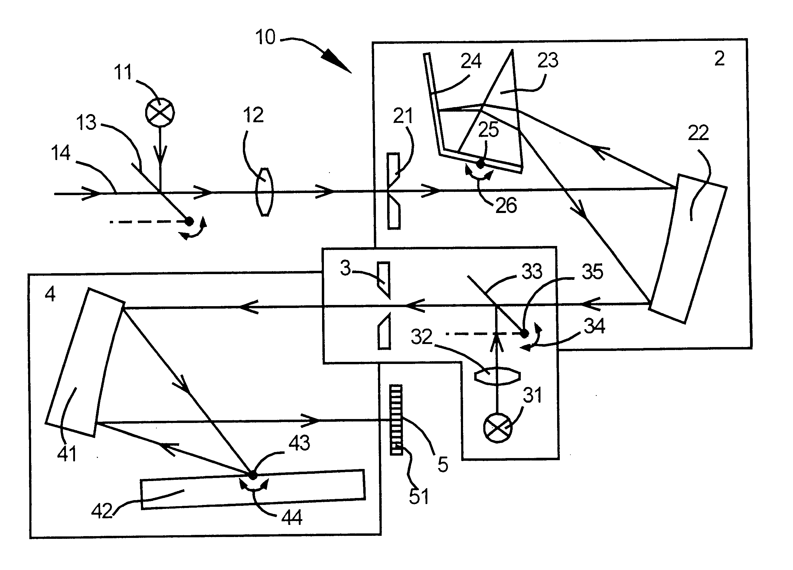
[0030] In FIG. 1 numeral 10 denotes a spectrometer assembly. The assembly 10 comprises a pre-monochromator 2 and an echelle spectrometer 4. Numeral 21 denotes the entrance slit of the pre-monochromator 2. It is illuminated by a light source 11 with a continuous wavelength spectrum for calibration. Such a light source is for example a Xenon high pressure short arc lamp. For this purpose a rotatable mirror 13 and a lens 12 are arranged in the measuring optical path 14 as an imaging element. The entrance slit 21 has a fixed slit width of 25 microns, corresponding to the width of a detector element 51 of a CCD-linear array 5 used as a spatially resolving light detector. The entrance slit 21 forms the field stop for the double spectrometer assembly and defines the width of a monochromatic beam at the location of the detector 5.

[0031] The incident divergent light beam is deflected and collimated by a paraboloidal mirror 22. The parallel light passes through a prism 23. Thereby the light ...


PUM


Abstract

A spectrometer assembly (10) comprises a light source (11) with a continuous spectrum, a pre-monochromator (2) for generating a spectrum with a relatively small linear dispersion from which a spectral portion is selectable, the spectral bandwidth of such spectral portion being smaller than or equal to the bandwidth of the free spectral range of such order in the echelle spectrum wherein the centre wavelength of the selected spectral interval is measurable with maximum blaze efficiency, an echelle spectrometer (4) with means for wavelength calibration, an entrance slit (21) at the pre-monochromator (2), an intermediate slit assembly (50) with an intermediate slit (3) and a spatially resolving light detector (5) in the exit plane of the spectrometer for the detection of wavelength spectra. The assembly is characterised in that the width of the intermediate slit (3) is larger than the monochromatic image of the entrance slit generated by the pre-monochromator at the location of the intermediate slit, and means for calibrating the pre-monochromator are provided, which are adapted to calibrate the light of the light source with a continuous spectrum on the detector to a reference position.

Description

TECHNICAL FIELD [0001] The invention relates to a spectrometer according to the preamble of claim 1. Furthermore, the invention relates to a method for the wavelength calibration of echelle spectrometers. [0002] Echelle spectrometers are spectrometers operating with an echelle grating. These gratings have a high angular dispersion, i.e. the ability to angularly separate closly proximate wavelengths. This has the advantage of a high resolution and yet small dimensions of the assembly. Therefore, echelle gratings are particularity suitable for high resolution spectroscopy, such as atomic absorption spectroscopy with continuous light sources. A spectrometer with an echelle grating normally operates in very high diffraction orders. Typical values are 20th to 150th order. The free spectral range in each order is comparatively small. [0003] In order to avoid spectral overlapping of different diffraction orders in the exit plane of the spectrometer, echelle spectrometers are used in combin...

Claims


Application Information

Patent Timeline
IPC IPC(8): G01J3/02G01J3/04G01J3/08G01J3/12G01J3/14G01J3/18G01J3/28
CPCG01J3/02G01J3/0229G01J3/04G01J3/08G01J2003/2866G01J3/1809G01J3/28G01J2003/1208G01J3/14
Inventor FLOREK, STEFANBECKER-ROSS, HELMUTHEITMANN, UWE
Owner LEIBNIZ - INSTITUT FUER ANALYTISCHE WISSENSCHAFTEN ISAS
Why Eureka
Try Eureka