[0017] A strain gauge is disclosed that is or can be installed on a deformable body of a force-measuring cell, wherein a protective coating is provided which on the one hand prevents
moisture from entering and on the other hand avoids or at least significantly reduces bypass forces.
[0019] The excellent barrier properties that are found in the inorganic materials are exploited and, by using very thin barrier coatings, a reduction of the very
high stiffness associated with the thick inorganic coatings that are known from the existing state of the art is achieved. In order to avoid the aforementioned bypass forces, a coating thickness is selected primarily in the sub-micron range, because the inorganic materials, as is commonly known, have a modulus of elasticity that is larger by a factor of 10 to 100 than the
elastic modulus of
polymer materials of the kind that are used, e.g., for the carrier substrate. With a low thickness, it is possible to reduce the stiffness of the protective layer which, as is commonly known, depends on the
elastic modulus of a material and on the thickness of a coating made of the material.
[0023] It is an exemplary property of the protective coating, specifically of individual
layers of the latter, that the coating in the process of being deposited, particularly by PECVD (
plasma-enhanced
chemical vapor deposition), grows in a conformal way on the underlying surface, i.e., as a so-called
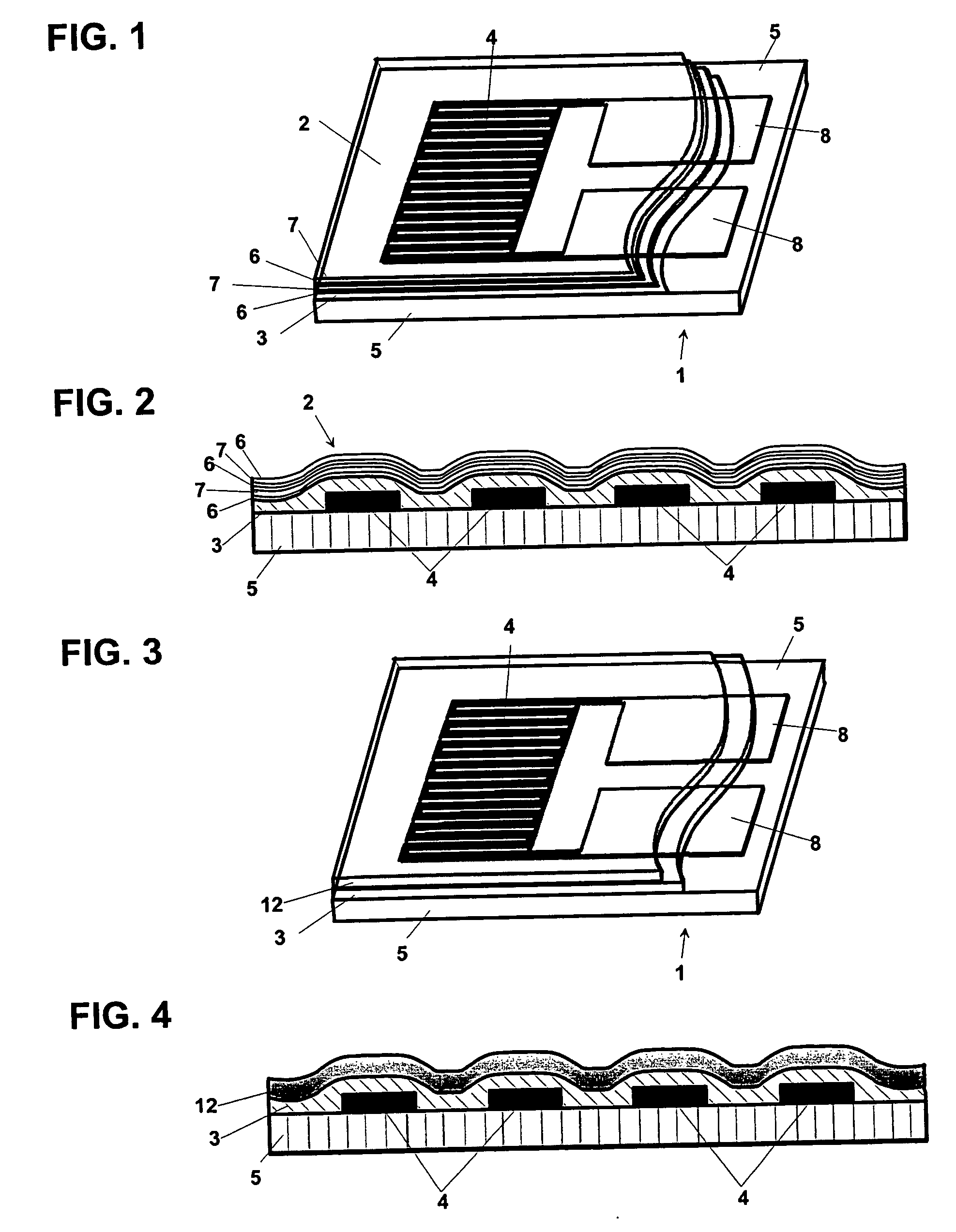
conformal coating. This means that the surface receives a coverage of substantially constant thickness, independent of the angles at which individual surface locations are oriented in relation to the overall orientation of the deposition surface (plane of deposition). In other words, even overhanging portions or portions that substantially extend at a right angle to the deposition plane, for example the lateral flanks of the resistor track, are covered by the protective coating. In combination with the surface-smoothing
polymer layer as an underlying base, an optimum of protection is achieved against the penetration of
moisture. The polymer layer used as an undercoating under the protective coating has the effect of smoothing
rough surface areas and
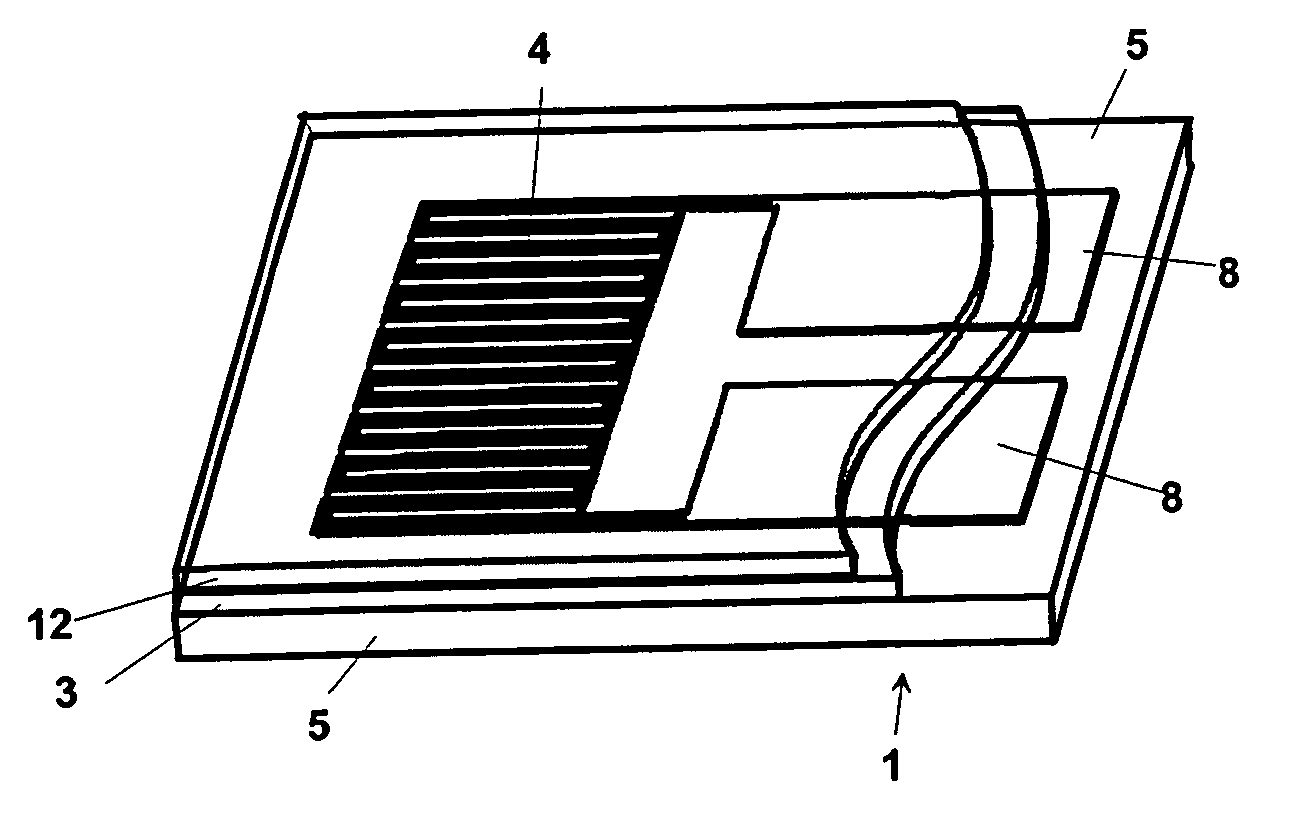
rounding out edges where an inorganic protective coating has a particular tendency to develop the aforementioned micro-pores or micro-breaks, or hairline breaks that occur as a result of locally concentrated stresses, particularly thermal stresses, and where also on the other hand a tendency exists for micro-pores or micro-breaks to attach themselves. Thus, the occurrence of micro-pores or micro-fractures in the protective coating is a priori reduced, and while the edges still have a degree of steepness, they are not excluded from coverage by the protective coating, due to the conformance of coating to the underlying surface. Thus, the surface area of the strain gauge is covered completely and uniformly by the protective coating, and there are no weak spots where moisture could enter. In addition to the aforementioned complete coverage of the resistor track, the absence of weak spots is also of
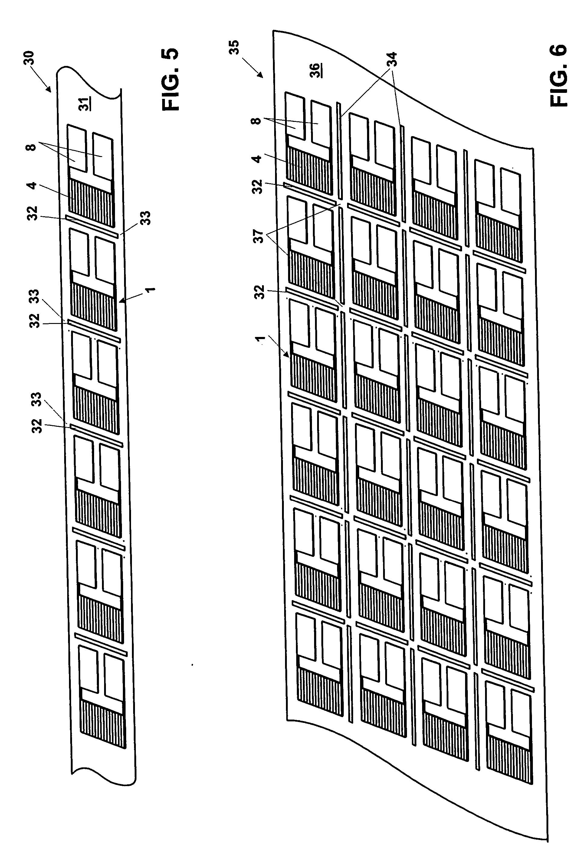
advantage in cases where the strain gauge is applied to a force-measuring cell and subsequently coated, or in a single-row array or a two-dimensional array of strain gauges in which the border surfaces of the carrier substrate are already substantially exposed by slits which were
cut in the array to allow the border surfaces to be covered in the coating process.
[0029] This continuous variation can occur on the one hand in multilayered coatings as a soft transition between the individual
layers, i.e., the coating parameters are not changing abruptly, but their profile is a continuous periodic function, rather resembling a sine function. On the other hand, the inhomogeneity can occur in a
continuous transition over the entire thickness of the coating, as a gradient of one or more of the coating material parameters. This version of a continuous variation is, for example, advantageous for producing extremely thin protective coatings that are used on strain gauges for force-measuring devices of high sensitivity and a
low load capacity.
[0031] An
advantage of an inhomogeneous protective coating with a continuous variation of one or more parameters, whether the continuous variation has the form of a gradient or of continuous transitions between the
layers of a multilayered coating, lies in a further reduction of internal stresses which could otherwise occur if layers with strongly different parameters followed each other abruptly in a multilayered coating, where the risk of a
delamination of individual layers would not in all cases be excluded.
[0032] Accordingly, an
advantage of a protective coating with a continuous variation of a parameter lies in a
reduced risk of
delamination. In contrast, an advantage of a multilayered coating with abrupt transitions between the layers lies in the fact that if a first layer, e.g., a
barrier layer, is followed immediately by a second layer, e.g., an intermediate layer, with parameters different from the first layer, the micro-pores and micro-breaks of the first layer are almost completely covered, whereby an improved
barrier effect is achieved.

