Phase change sensor

a phase change sensor and sensor technology, applied in the direction of instruments, biomass after-treatment, analysis using chemical indicators, etc., can solve the problems of unresolved noise problems along the connecting wire, the replacement of the probe in some spm designs may take many minutes, and the exterior transfer and processing circuit occupies a relatively large space, so as to achieve enhanced device selectivity, high-sensitivity and selective sensor

Inactive Publication Date: 2005-07-28
CANTIMER
View PDF63 Cites 100 Cited by
  • Summary
  • Abstract
  • Description
  • Claims
  • Application Information

AI Technical Summary

Benefits of technology

[0023] A device is disclosed which is a highly sensitive and selective sensor. The device is comprised of a sensor material secured into a fixed position on a substrate, a deformable arm and a signaling component which creates a detectable signal in response to movement of the arm. The sensitivity of the device is enhanced by using a sensor material which undergoes a dramatic change in volume such as a phase change in response to a target molecule of interest. The selectivity of the device is enhanced by incorporating highly specific binding receptors (e.g. antibodies) into the sensor material which receptors bind to specific targets (e.g. peptide epitopes). The binding of the target molecule to the receptor causes sensor material to undergo a phase change which moves the arm causing the signaling component (e.g. a piezoresistor) to create a detectable signal (e.g. change in resistance) thereby indicating the present of the target.

Problems solved by technology

Because of the delicate nature of the probes and the alignment described below, replacement of the probe in some SPM designs may take many minutes, as described in U.S. Pat. No. 5,376,790, assigned to Park Scientific Instruments.
U.S. Pat. No. 5,266,801 makes use of the piezoelectric or piezoresistive materials to measure the strain on the cantilever, but it still has the noise problem left irresolvable for the signal along the connecting wire.
Also, the exterior transfer and processing circuit occupies a relatively large space and complicates the system structure.
Similar to other prior art Atomic Force Microscopes, since they have many optical elements, their system spaces are relatively large, their structures are relatively complicated, and the noise problems of their connecting wires still exist.
Although many different kinds of mechanical oscillators currently exist, some are less useful for measuring properties of liquid solutions.
For example, ultrasonic transducers or oscillators cannot be used in all liquids due to diffraction effects and steady acoustic (compressive) waves generated within the reactor vessel.
Unfortunately, complex liquids and mixtures, including polymer solutions, often behave like elastic gels at these high frequencies, which results in inaccurate resonator response.
Unfortunately, the operating frequency of these sensors is also high, which, as mentioned above, restricts their use to simple fluids.
Moreover, at high vibration frequencies, most of the interaction between the sensor and the fluid is confined to a thin layer of liquid near the sensor surface.
Any modification of the sensor surface through adsorption of solution components will often result in dramatic changes in the resonator response.

Method used


Image

  • Phase change sensor
  • Phase change sensor
  • Phase change sensor

Examples


specific embodiments

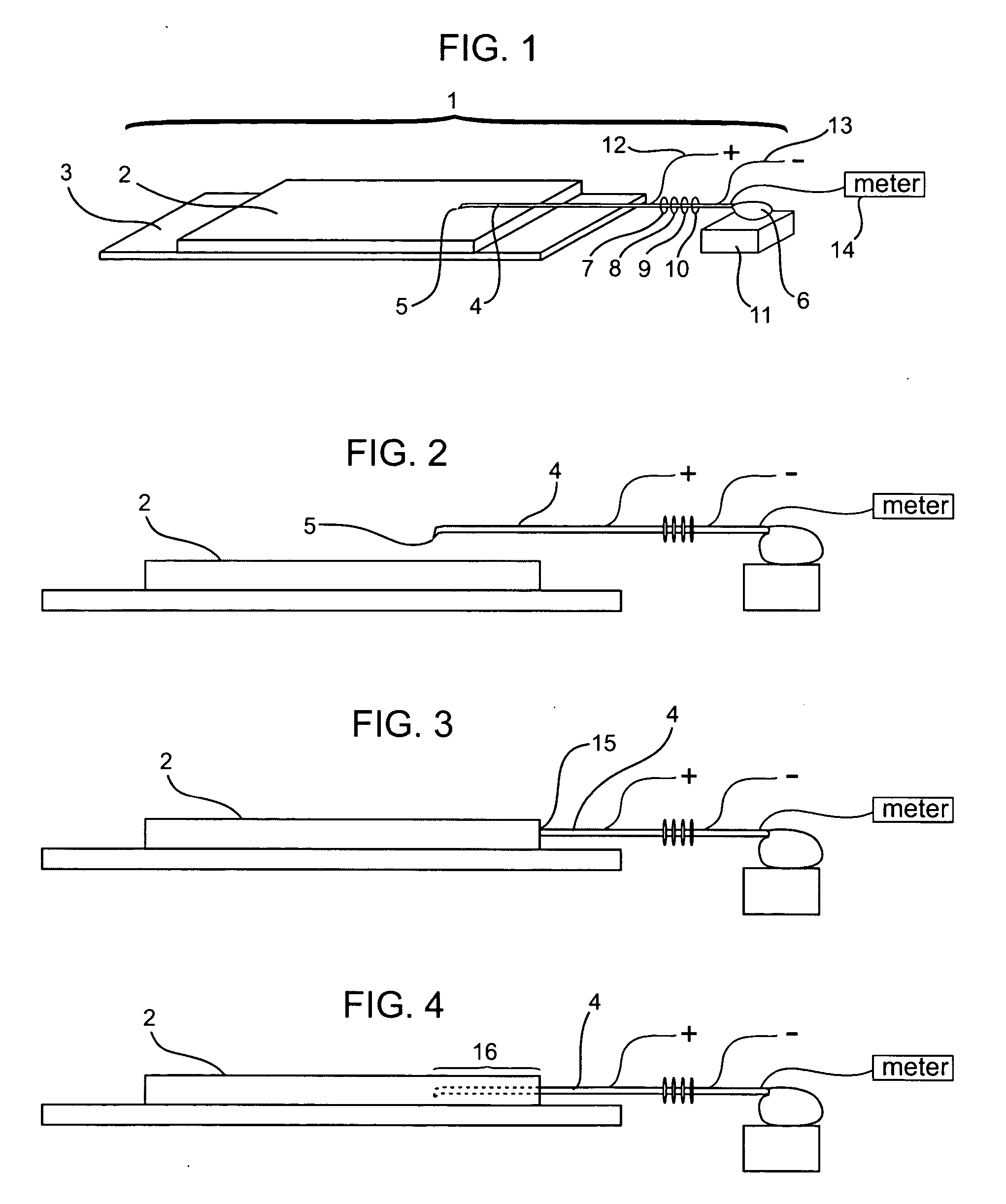
[0086]FIG. 1 shows a perspective, schematic view of an embodiment of a sensor device 1 of the invention. The device 1 is comprised of a sensor material 2 connected, secured, attached or anchored in place in some manner such as to a substrate 3. An arm 4 is positioned over the sensor material 2 and an end 5 of the arm 4 is positioned very close to a surface of the sensor material 2 such as 1 mm or less, or 0.1 mm or less or 1 micrometer or less. Thus, when the sensor material 2 expands it moves the end 5 of the arm 4. Conventional microcantilever sensor devices are disclosed in U.S. Pat. No. 6,523,392 issued Feb. 25, 2003 and U.S. Patent Publication No. 2003 / 0010097 published Jan. 16, 2003. These designs may be changed to include sensor material 2 of the present invention.

[0087] The arm 4 may be comprised of a suitable material such as silicon or variation or analog thereof such as silicon nitride which may be heated and drawn into a thin strand. The arm 4 may be formed from and int...

example 1

Hydrogel Polymer

[0129] Polymer is prepared comprising hydroxypropyl acrylate having a MW of between 200,000 and 500,000 daltons. The resulting polymer is washed with ethyl actetate to remove residual monomer and taken up in a 1:1 mixture of ethyl acetate: tetrahydrofuran at 25% solids.

[0130] To a 3 grams polymer solids sample is added 0.2% w / w PFAZ 233 polyfunctional crosslinking agent (BAYER) and cast onto glass petri dishes. The polymer is allowed to crosslink and dried at 90 C for 12 hours.

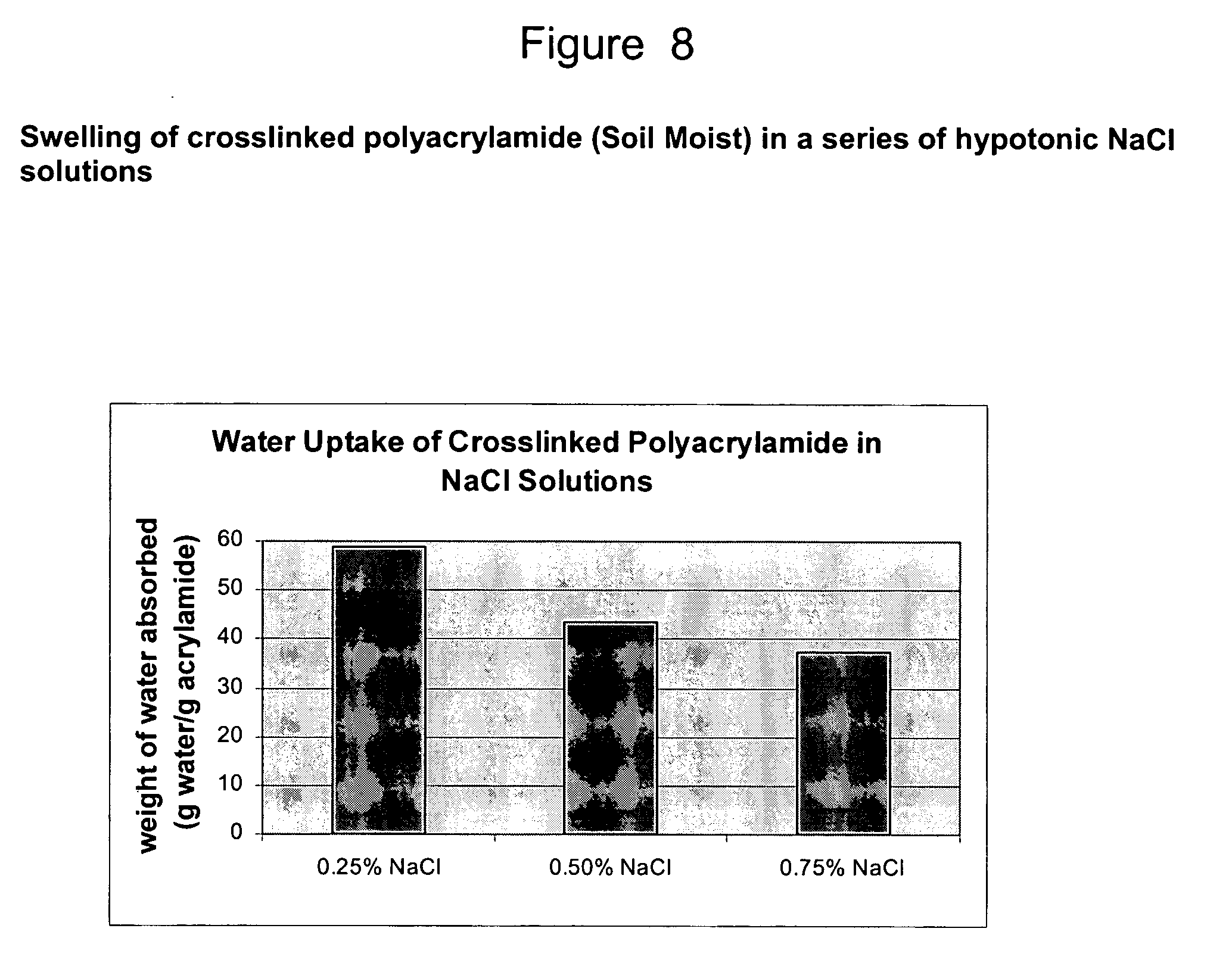
[0131] The water uptake of the polymer is measured at varying osmolalities and seen to be highly responsive to changes in osmotic properties. Further details regarding hydrogel polymers are provided below in Example 8.

example 2

Osmolality Sensor

[0132] Polymer solution as above is diluted to 10% solids and a 1.0 mm thick glass chip is dip coated with the solution and dried. The resulting polymer film is approximately 25 microns thick. A piezoresistive microcantilever (Veeco) (and it's electrical contacts including solder wires) is dip coated with a 10% solids solution of 2 part epoxy twice and dried at 90° C. The cantilver is then mounted proximate to the glass chip such that the cantilever is just touching the surface of the polymer. The resulting assembly is dip coated a second time to embedd the cantilever.

[0133] The sensor responds predictibly to changes in osmolality in the range of interest for human saliva (50-200 mOsmol). Further details on such a sensor are provided below in Example 8.


PUM

PropertyMeasurementUnit
thicknessaaaaaaaaaa
lengthaaaaaaaaaa
widthaaaaaaaaaa

Abstract

A device is disclosed which is a highly sensitive and selective sensor. The device is comprised of a sensor material secured into a fixed position on substrate, a deformable arm and a signaling component which creates a detectable signal in response to movement of the arm. The sensitivity of the device is enhanced by using a sensor material which undergoes a dramatic change in volume which may be accompanied by a phase change in response contact with a target such a molecule of interest. The selectivity of the device is enhanced by incorporating highly specific binding receptors (e.g. antibodies) into the sensor material which receptors bind to specific targets (e.g. peptide epitopes). The binding of the target molecule to the receptor causes the sensor material to change dramatically in volume thereby moving the arm causing the signaling component (e.g. a piezoresistor) to create a detectable signal (e.g. change in resistance) thereby indicating the present of the target.

Description

CROSS-REFERENCE [0001] This application claims the benefit of U.S. Provisional Application No. 60 / 475,637, filed Jun. 3, 2004 which application is incorporated herein by reference.FIELD OF THE INVENTION [0002] This invention relates generally to the field of high sensitivity sensors and detection devices and more specifically to such devices which include a MEMS detector, such as a cantilever arm. BACKGROUND OF THE INVENTION [0003] Non-aligned probes have been developed for atomic force microscopy (AFM), including strain gauge cantilever probes containing piezoelectric or piezoresistive material which produces a change in voltage or resistance in response to cantilever bending. Such probes were first disclosed in U.S. Pat. Nos. and 5,229,606 and 5,266,801 and have since also described in U.S. Pat. Nos. 5,345,816, 5,345,815 and 5,321,977. Non-aligned STM probes and piezoresistive cantilever probes are used in the AutoProbe.TM. VP UHV AFM / STM sold by Park Scientific Instruments. [0004...

Claims


Application Information

Patent Timeline
Patent Type & Authority Applications(United States)
IPC IPC(8): C12M1/34C12M3/00C12Q1/68G01N7/00G01N21/00G01N25/18G01N31/22G01N33/53G01N33/544G01N33/545G01N33/546G01N33/549G02B
CPCB82Y5/00G01N33/54373B82Y15/00
Inventor STEWART, RAY F.
Owner CANTIMER
Why Eureka
Try Eureka