Method of producing crystalline semiconductor material and method of fabricating semiconductor device

Inactive Publication Date: 2005-08-11
SONY CORP
View PDF4 Cites 23 Cited by
  • Summary
  • Abstract
  • Description
  • Claims
  • Application Information

AI Technical Summary

Benefits of technology

[0014] In accordance with the method of producing a crystalline semiconductor material according to the first aspect and the method of fabricating a semiconductor device according to the third aspect, since the amorphous material or the polycrystalline material are uniformly heat-treated by a plurality of times at such a temperature as to partially melt crystal grains having a specific face orientation with respect to the vertical direction of the surface of the substrate and melt the amorphous material or crystal grains having a face orientation other than the specific face orientation, it is possible to form a crystalline material which has crystal grains preferentially grown in the specific face orientation with respect to the vertical direction of the substrate and thereby has sharp crystal grain boundaries, and hence to improve the crystallinity of the crystalline material.
[0015] In accordance with the method of producing a crystalline semiconductor material according to the second aspect and the method of fabricating a semiconductor device according to the fourth aspect, in the second step, a first crystalline material is formed by uniformly heat-treating the amorphous material or the polycrystalline material by a plu

Problems solved by technology
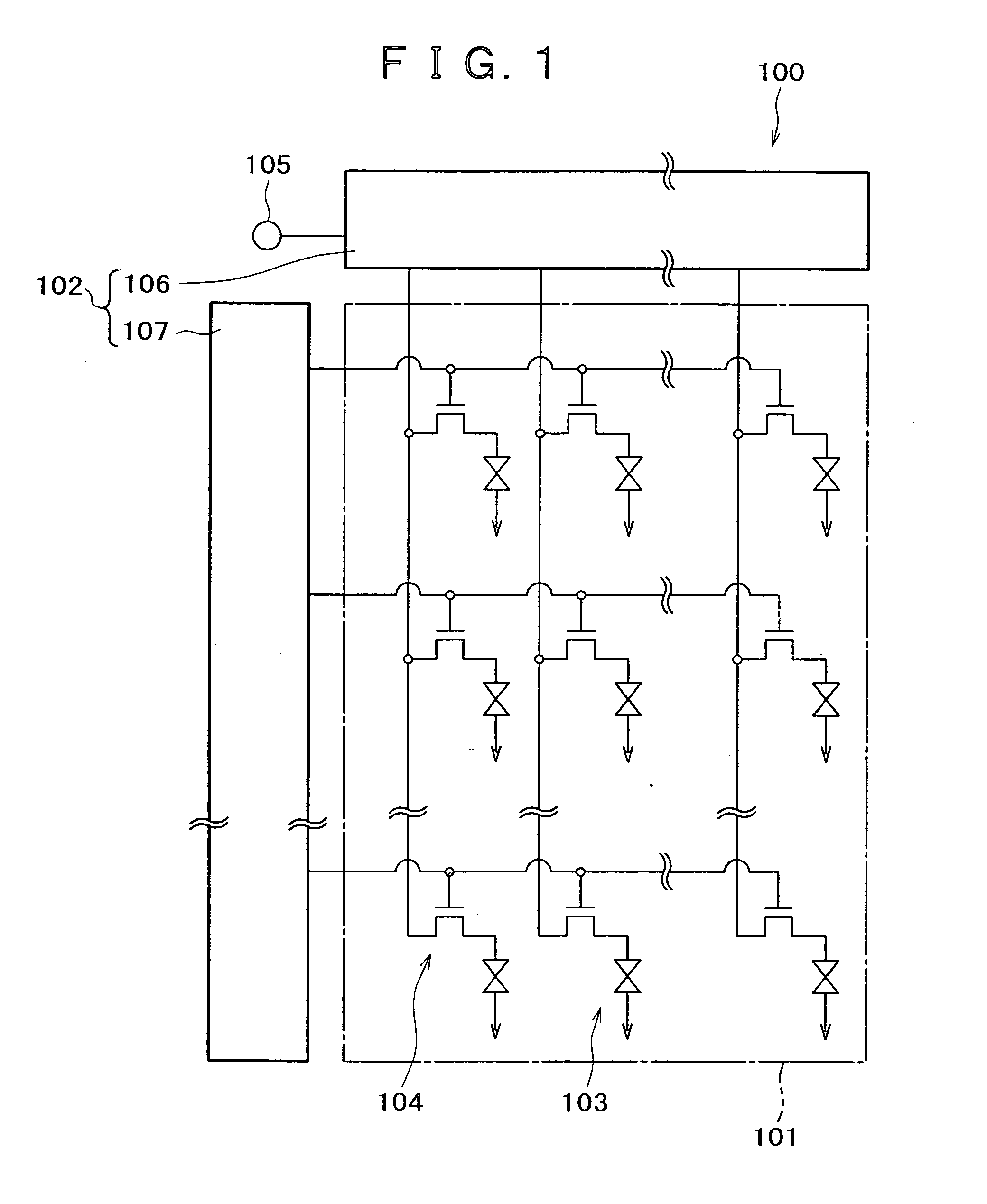
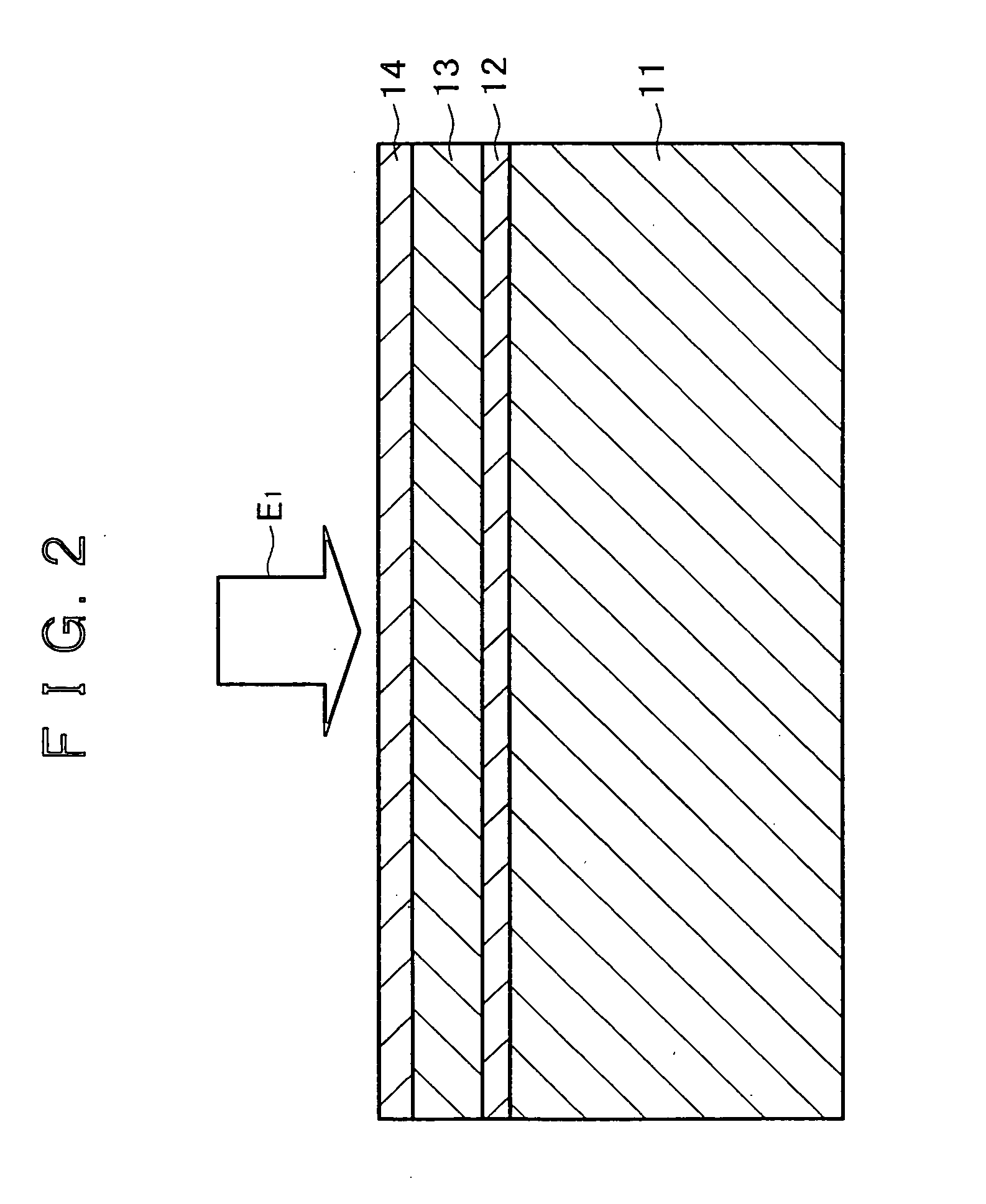
The use of the polycrystalline silicon film for forming the operational region, however, has a disadvantage that the crystallinity of the polycrystalline silicon film is poor because crystal grains boundaries are present at random in the fine structure of the film and crystal grains have different face orientations.
Another disadvantage is that as the grain sizes of crystal grains in the polycrystalline silicon film become as large as being close to the channel length of the TFT, the characteristics of the TFT may become uneven.
In this way, a semiconductor device such as a TFT using a polycrystalline silicon film is very inferior in characteristics to a semiconductor device using a single crystal silicon film.
The ZMR technique allows formation of a silicon film having a large area, but has a difficulty in control of orientation of crystal grains and crystal grain boundaries.
Accordingly, a silicon film formed by the ZMR technique contains crystal grain boundaries that are present at random, and is therefore difficult to be applied to three-dimensional integration of semiconductor devices, which integration requires a high-level equalization of the semiconductor devices.
Another proble

Method used


Image

  • Method of producing crystalline semiconductor material and method of fabricating semiconductor device
  • Method of producing crystalline semiconductor material and method of fabricating semiconductor device
  • Method of producing crystalline semiconductor material and method of fabricating semiconductor device

Examples


Example

EXAMPLE

[0104]FIG. 13A is a SEM (Scanning Electron Microscope) photograph of a crystalline film obtained by the first heat-treatment under the following conditions. FIGS. 13B and 13C are EBSP (Electron Back Scattering Pattern) photographs of the crystalline film in a normal direction and a rolling direction, respectively. FIG. 14 is a graph indicating the degrees of the {100} orientations with respect to the vertical direction of a glass substrate after repetition of pulse laser irradiation by 150 times, and FIG. 15 is a graph indicating the degrees of the {100} orientations with respect to the vertical direction of the glass substrate after repetition of pulse laser irradiation by 200 times. FIG. 16 is a view illustrating the normal direction (vertical direction of the glass substrate) and the rolling direction (in-plane direction of the glass substrate) shown in FIGS. 13B and 13C.

[0105] In addition, before the SEM photograph of the crystalline film is taken, the crystalline film ...


PUM

PropertyMeasurementUnit
Timeaaaaaaaaaa
Temperatureaaaaaaaaaa
Crystallinityaaaaaaaaaa

Abstract

Disclosed are a method of producing a crystalline semiconductor material capable of improving the crystallinity and a method of fabricating a semiconductor device using the crystalline semiconductor material. An amorphous film is uniformly irradiated with a pulse laser beam (energy beam) emitted from an XeCl excimer laser by 150 times so as to heat the amorphous film at such a temperature as to partially melt crystal grains having the {100} orientations with respect to the vertical direction of a substrate and melt amorphous film or crystal grains having face orientations other than the {100} orientations. Silicon crystals having the {100} orientations newly occur between a silicon oxide film and liquid-phase silicon and are bonded to each other at random, to newly form crystal grains having the {100} orientations. Such a crystal grain creation step is repeated, to form a crystalline film which has crystal grains preferentially grown in the {100} orientations with respect to the vertical direction of the substrate and thereby has sharp square-shaped crystal grain boundaries.

Description

BACKGROUND OF THE INVENTION [0001] The present invention relates to a method of producing a crystalline semiconductor material by heating an amorphous semiconductor material or a polycrystalline semiconductor material so as to crystallize the material, and a method of fabricating a semiconductor device using such a crystalline semiconductor material. [0002] In recent years, semiconductor devices used, for example, for a solar cell including such semiconductor devices formed on a substrate in an array pattern and for a liquid crystal display unit including such semiconductor devices as pixel drive transistors have been actively studied and developed. Further, in recent years, to realize a high degree of integration and multi-function of semiconductor devices, a three-dimensional integrated circuit including the semiconductor devices stacked on a substrate has been actively studied and developed. [0003] A glass material such as artificial quartz or a plastic material has drawn attenti...

Claims


Application Information

Patent Timeline
IPC IPC(8): G02F1/1368C23C14/14C23C14/34C23C14/58C23C16/24C23C16/26C23C16/28C23C16/56C30B13/00C30B13/24G09G3/36H01L21/20H01L21/336H01L29/786
CPCC30B13/00C30B13/24C30B13/34C30B29/06H01L21/02529H01L27/1285H01L21/02609H01L21/02686H01L29/04H01L21/02532C30B29/08H01L21/20
Inventor GOSAIN, DHARAM PALMACHIDA, AKIONAKANO, KAZUSHIFUJINO, TOSHIOSATO, JUNICHI
Owner SONY CORP
Why Eureka
Try Eureka