Flying capacitor type battery voltage detector

a capacitor type, battery voltage detector technology, applied in the direction of electronic devices, printed circuit non-printed electric components association, instruments, etc., can solve the problems of inability to dispose the photo mos switch in the integrated circuit as non-discrete units, the signal-to-noise ratio in each signal is undesirably lowered or degraded, and the degree of amplification factor reduction of the output voltage of the cell can be reduced, and the s/n ratio can be improved

Active Publication Date: 2005-09-01
DENSO CORP
View PDF4 Cites 27 Cited by
  • Summary
  • Abstract
  • Description
  • Claims
  • Application Information

AI Technical Summary

Benefits of technology

[0018] An object of the present invention is to provide, with due consideration to the problems of the conventional flying capacitor type battery voltage detector, a flying capacitor type battery voltage detector in which an SN ratio of a signal indicating a voltage created in each of cells of a battery pack is improved.

Problems solved by technology

In addition, because the same battery voltage detector is used for the cells of the battery pack, a degree of an error of an amplification factor and a degree of an offset error caused by the differential amplifier are substantially invariable in the detecting operations of the output voltages of the cells of the battery pack.
Therefore, it is difficult to dispose the photo MOS switches in an integrated circuit as non-discrete units.
However, the above-described battery voltage detector has the following problems.
As a result, noises in voltage are superimposed on signals indicating the output voltages of the cells because of a large temperature difference in the circuit area of the multiplexer, and a signal-to-noise (SN) ratio in each signal is undesirably lowered or degraded (first problem).
As a result of the occurrence of the coupling and / or the reception of the external electromagnetic waves, the electric potential of the flying capacitor side wire set at the floating potential condition is easily changed, and the voltage applied to the flying capacitor is undesirably changed with the electric potential of the flying capacitor side wire.
Therefore, the SN ratio is further degraded (second problem).
Further more, because the multiplexer is disposed in a wide area of the circuit substrate, the cell side wires and the flying capacitor side wires connected with the multiplexer are inevitably lengthened.
Therefore, the flying capacitor sometimes is not sufficiently charged to detect the output voltage of each cell in the differential amplifier.
As a result, the SN ratio deteriorates.
Moreover, as well known, noises based on the resistance of each wire are increased with the wiring resistance, so that the SN ratio is further lowered (third problem).
As a result, it is difficult to reduce the wiring resistances of the potential detecting substrate surface lines and the flying capacitor side lines, and the SN ratio is further lowered (fourth problem).
Therefore, the same problems described above occur in this circuit.

Method used


Image

  • Flying capacitor type battery voltage detector
  • Flying capacitor type battery voltage detector
  • Flying capacitor type battery voltage detector

Examples


embodiment 1

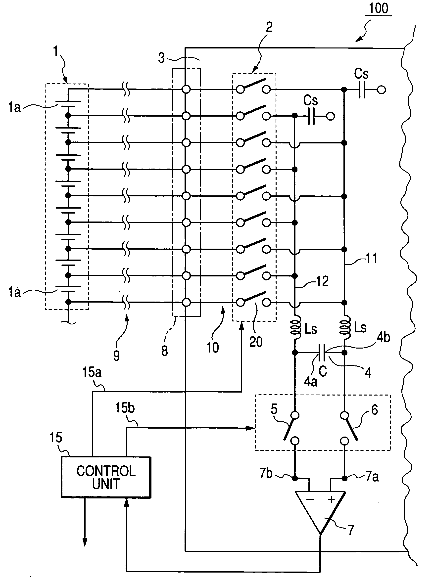
[0061]FIG. 1 is a circuit view showing a flying capacitor type battery voltage detector according to a first embodiment.

[0062] As shown in FIG. 1, a battery pack 1 has a plurality of cells 1a connected with one another in series, and a potential detecting line 9 made of a cable extends from each of terminals of the cells 1a. The battery pack 1 has 384 cells 1a, and a part of the cells 1a are shown in FIG. 1. The number of potential detecting lines 9 is higher than the number of cells 1a by one. The cells 1a are numbered in an order of lowering an electric potential. The top potential detecting line 9 extends from a positive terminal of the top cell 1a at the highest electric potential, and the final potential detecting line 9 (not shown) extends from a negative terminal of the final cell 1a (not shown) set at the lowest electric potential. The electric energy created by the battery pack 1 is used to run a hybrid vehicle.

[0063] A flying capacitor type battery voltage detector 100 m...

embodiment 2

[0099] Another arrangement of the flying capacitor type battery voltage detector 100 according to the second embodiment is described with reference to FIGS. 5 and 6.

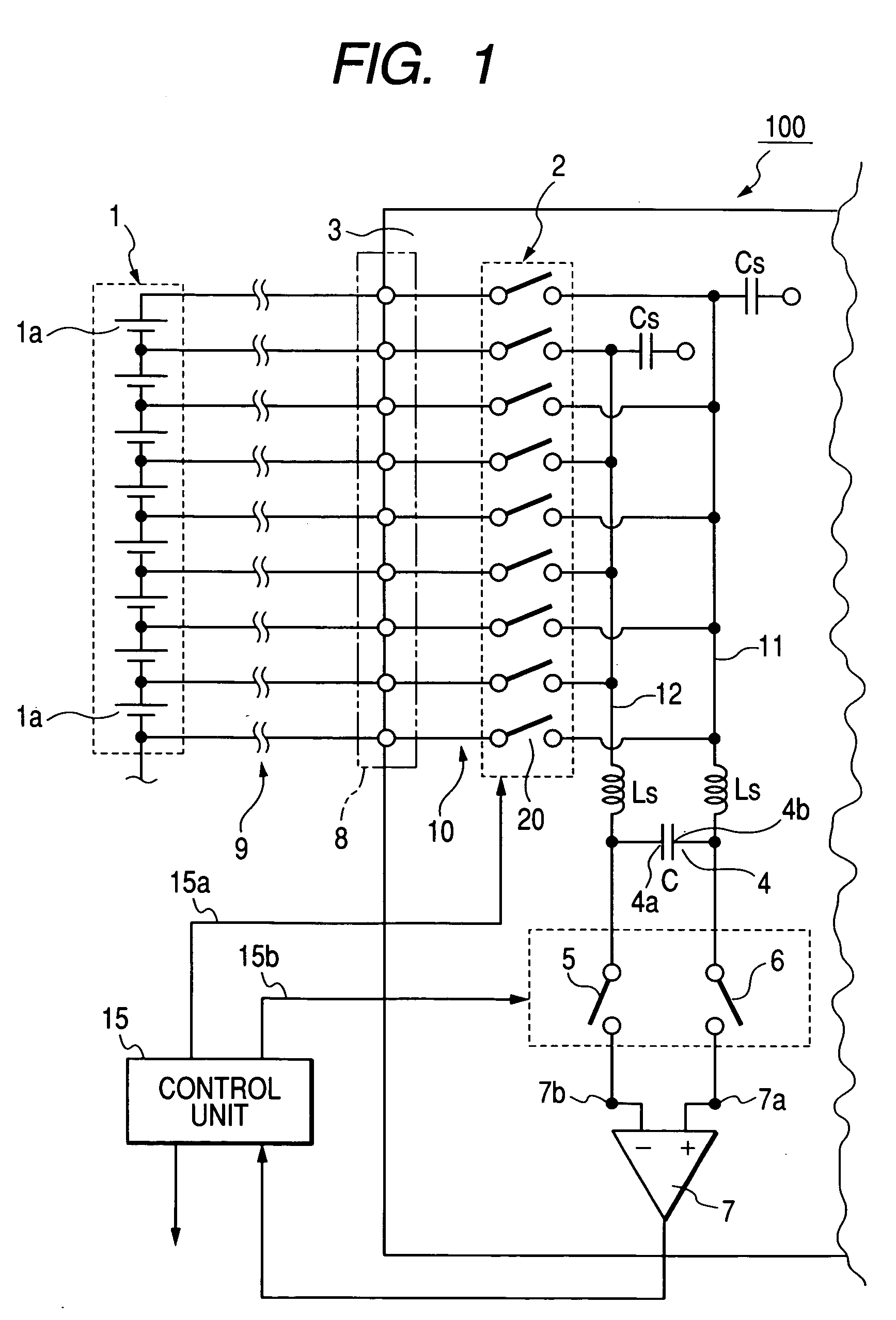
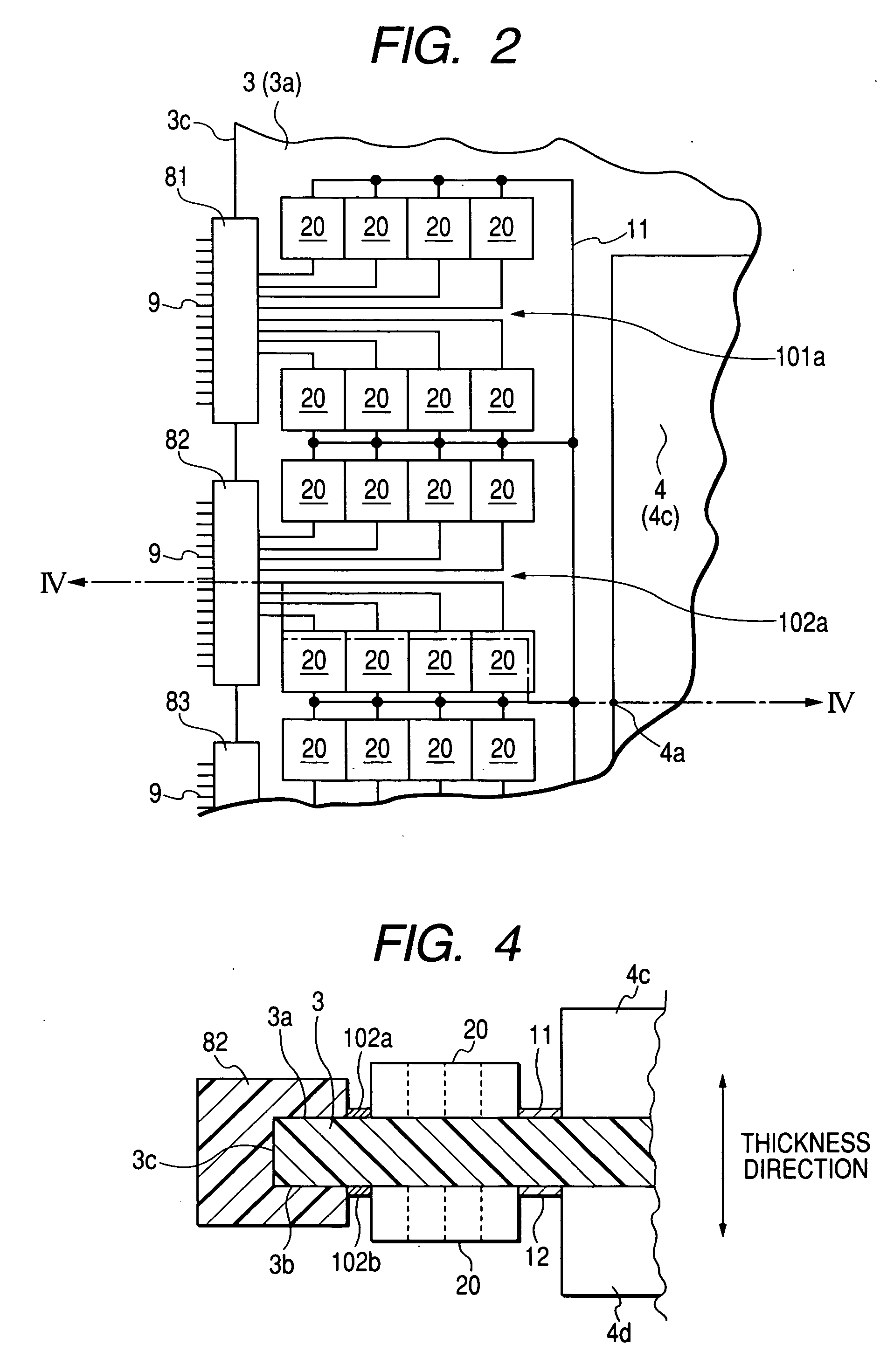
[0100]FIG. 5 is a partial plan view schematically showing an arrangement of constitutional elements disposed on each of the front and back surfaces of the circuit substrate in the flying capacitor type battery voltage detector shown in FIG. 1 according to the second embodiment. FIG. 6 is a partial vertical cross-sectional view taken substantially along line VI-VI of FIG. 5.

[0101] As shown in FIG. 5 and FIG. 6, on the front surface 3a of the circuit substrate 3, the odd-numbered photo MOS switches 20 are placed between the group of first potential detecting substrate surface lines 10 (101a, 102a, - - - ) and the first flying line 11, and the first potential detecting substrate surface lines 101a, 102a, - - - are placed between the connector section 8 of the connectors 81, 82, - - - and the odd-numbered photo MOS switche...


PUM

PropertyMeasurementUnit
angleaaaaaaaaaa
thicknessaaaaaaaaaa
electric energyaaaaaaaaaa

Abstract

In a flying capacitor type battery voltage detector on a circuit substrate, a large number of photo MOS switches having performance highly depending from temperature are dividedly disposed on front and back surfaces of the circuit substrate such that the photo MOS switches of the back surface are lying over the photo MOS switches of the front surface. Each of pairs of photo MOS switches connects a pair of surface lines with first and second floating lines to transmit an output voltage of each cell of a battery pack connected with the surface lines to a differential amplifier through a flying capacitor connected with the floating lines. Because of the division of the photo MOS switches on the surfaces of the circuit substrate, temperatures of the photo MOS switches have less dispersion, and an S / N ratio of each signal indicating the output voltage can be improved.

Description

CROSS-REFERENCE TO RELATED APPLICATION [0001] This application is based upon and claims the benefit of priority of the prior Japanese Patent Application 2004-10869 filed on Jan. 19, 2004 so that the contents of which are incorporated herein by reference. BACKGROUND OF THE INVENTION [0002] 1. Field of the Invention [0003] The present invention generally relates to a flying capacitor type battery voltage detector mounted on a vehicle, and more particular to a flying capacitor type battery voltage detector in which voltages created by cells of a battery pack is detected one by one in a predetermined order to check the performance of each cell. [0004] 2. Description of Related Art [0005] A battery pack creating a high voltage has generally been used in a hybrid vehicle or a fuel cell electric vehicle to reduce a power loss in wires and to lessen weight of cables. The battery pack is composed of hundreds of cells connected with one another in series. In the vehicle using this battery pac...

Claims


Application Information

Patent Timeline
Patent Type & Authority Applications(United States)
IPC IPC(8): G01R31/36B60L3/00G01N27/416G01R15/16G01R19/00H05K1/18
CPCG01R15/16G01R19/0084H05K1/181G01R31/3658G01R31/362G01R31/3835G01R31/396
Inventor SHIMIZU, TAKUMIKOBAYASHI, TETSUYATANIGAWA, KEISUKE
Owner DENSO CORP
Why Eureka
Try Eureka