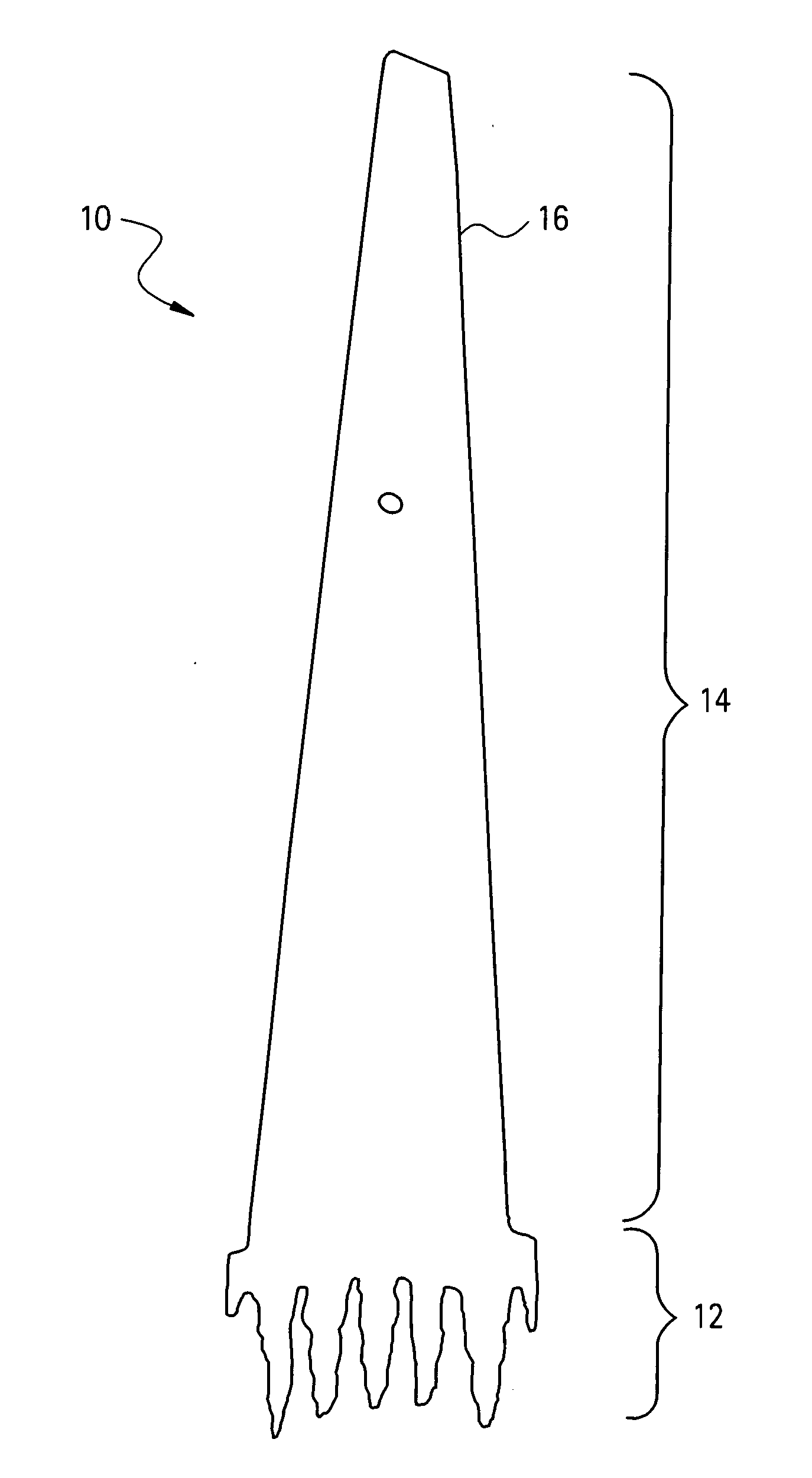
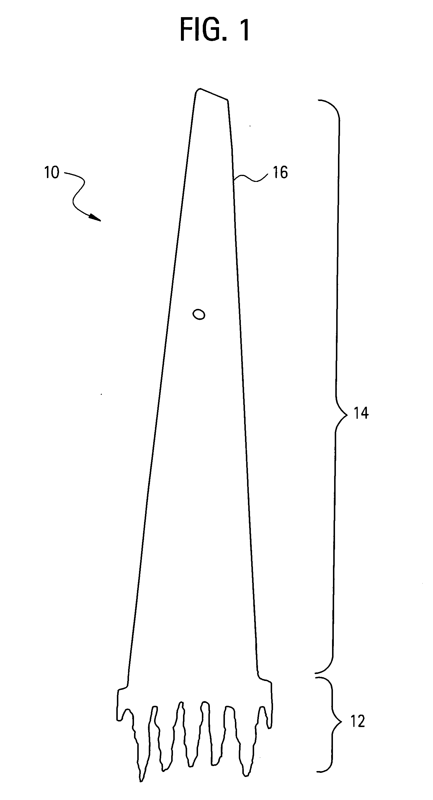
Erosion and wear resistant protective structures for turbine engine components

a protective structure and turbine engine technology, applied in the direction of liquid fuel engine components, non-electric welding apparatus, non-positive displacement fluid engines, etc., can solve the problems of power loss, progressive loss of bucket material, wear coating on turbine engine parts that are susceptible to wear,

Inactive Publication Date: 2005-09-22
GENERAL ELECTRIC CO
View PDF14 Cites 47 Cited by
  • Summary
  • Abstract
  • Description
  • Claims
  • Application Information

AI Technical Summary

Benefits of technology

[0008] A process for providing an erosion resistant protective structure to a turbine component comprises affixing a diffusion-controlling layer on a region of the turbine component to be protected with the erosion resistant protective structure, wherein the diffusion-controlling layer is selected from a group consisting of pure metals or alloys that do not form brittle and/or low melting phase due to interaction with erosion resistant structure and/or substrate; and affixing a shape memory alloy on the diffusion-controlling layer, wherein affixing the diffusion-controlling layer, and the shape memory alloy comprises a hot isotactic pressing process at a temperature less than about 950° C. and a pressure greater than about 20 ksi.
[0009] In another embodiment, a process for providing an erosion resistant protective structure to a turbine component comprises affixing a diffusion-controlling layer on a region of the turbine component to be protected with the erosion resistant protective structure, wherein the diffusion-controlling layer is selected from a group consisting of pure metals or alloys that do not form brittle and/or low melting phase due to interaction with erosion resis...

Problems solved by technology

Still another type of wear coating is placed on parts of the turbine engine that are susceptible to wear due to part-to-part contact during operation.
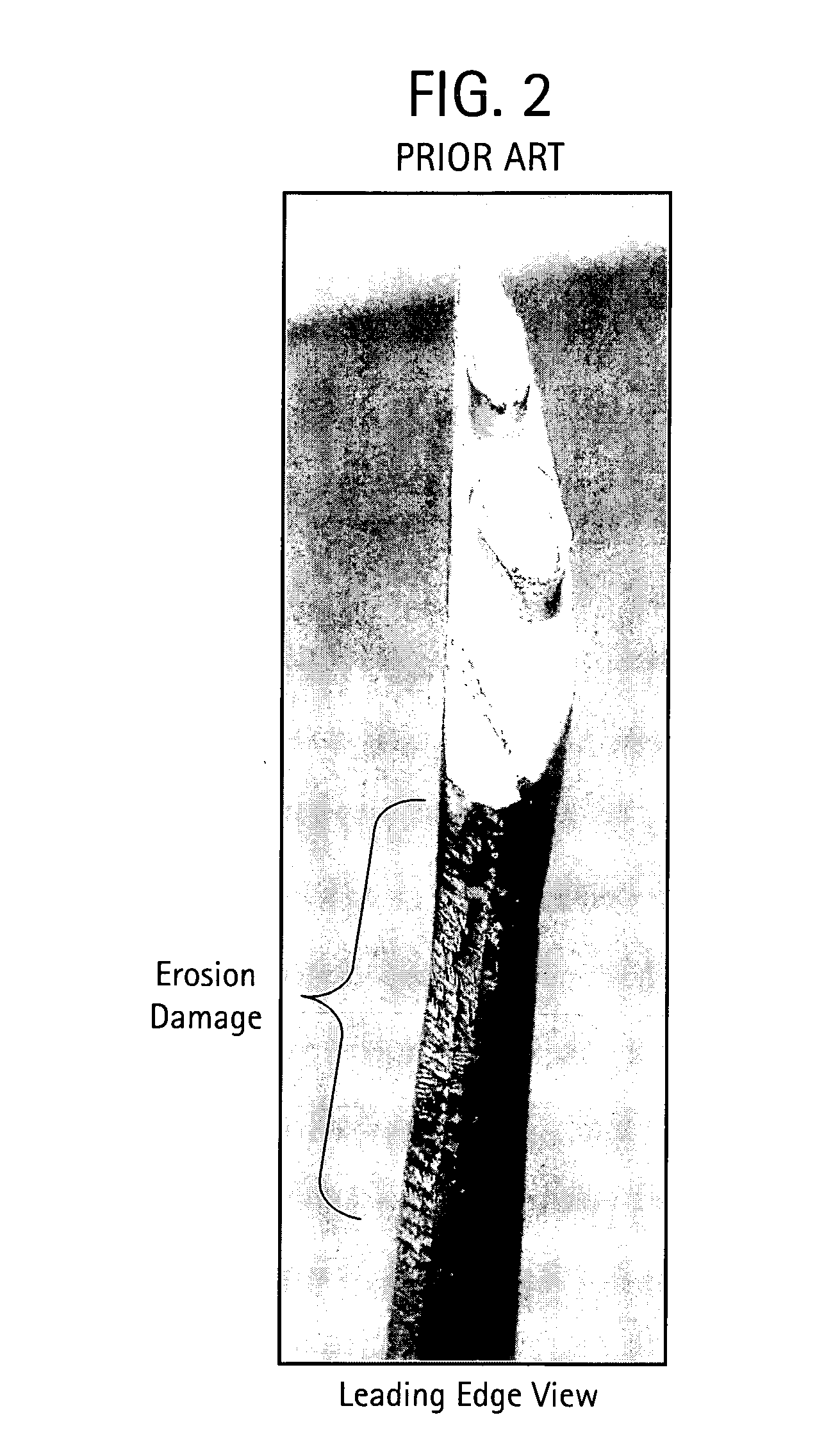
The impact of water drops generates an impulsive contact pressure on the blade material surface causing progressive loss of bucket material, i.e., erosion.
The resulting erosion of the steam turbine engine components can cause power loss, can effect turbine efficiency, and bucket lifetime...

Method used


Image

  • Erosion and wear resistant protective structures for turbine engine components
  • Erosion and wear resistant protective structures for turbine engine components
  • Erosion and wear resistant protective structures for turbine engine components

Examples


example 1

[0047] In this example, a NiTi shape memory alloy (56 wt % Ni, 44 wt % Ti) was joined to a Fe-based alloy using a HIP device at a temperature of 900° C. and a pressure of about 30 ksi. A cross section of the so-formed joint is illustrated in FIG. 4.

example 2

[0048] In this example, the NiTiCr shape memory alloy was joined to the Ti-based alloy with a Nb diffusion-controlling layer sandwiched therebetween. A cross section of the so-formed joint is illustrated in FIG. 5. No cracking is observed by optical and scanning electron microscopy and the joint formed appears to be firmly bonded.

example 3

[0049] In this example, a NiTiFe alloy (52 wt % Ni, 45 wt % Ti, and 3 wt % Fe) a Nb diffusion-controlling layer, and a Ti-based alloy were co-extruded using the extrusion process at a temperature of 900° C. and an area reduction ratio of 4:1. The NiTi based alloy and Ti-based alloy were preheated for 2 hours at a temperature of 900° C. A cross section of the so-formed joint is illustrated in FIG. 6. The interface between the NiTiFe and Ti-based alloy with the Nb diffusion-controlling layer appears uncracked and firmly bonded.


PUM

PropertyMeasurementUnit
Grain sizeaaaaaaaaaa
Temperatureaaaaaaaaaa

Abstract

An erosion resistant protective structure for a turbine engine component comprises a shape memory alloy. The shape memory alloy includes nickel-titanium based alloys, indium-titanium based alloys, nickel-aluminum based alloys, nickel-gallium based alloys, copper based alloys, gold-cadmium based alloys, iron-platinum based alloys, iron-palladium based alloys, silver-cadmium based alloys, indium-cadmium based alloys, manganese-copper based alloys, ruthenium-niobium based alloys, ruthenium-tantalum based alloys, titanium based alloys, iron-based alloys, or combinations comprising at least one of the foregoing alloys. Also, disclosed herein are methods for forming the shape memory alloy onto turbine component.

Description

BACKGROUND [0001] The present disclosure generally relates to erosion and wear resistant protective structures in the forms of coatings or shields for turbine engine components, and more particularly, to shape memory alloy protective structures for providing erosion resistance for turbine engine components. [0002] Erosion and wear resistant protective structures in the forms of coatings and shields have found various applications in turbine engines. For example, abrasive, wear-resistant coatings are frequently deposited on the outer tips of turbine blades. Such coatings are generally employed to decrease the rate of wear / erosion of the blade due to contact of the blade with its surrounding shroud. Other wear resistant coatings are placed on leading edges of turbine blades to decrease wear (by erosion) due to contact with environmental particulates (e.g., dirt, sand, and the like) that enter the turbine engine during operation. Still another type of wear coating is placed on parts of...

Claims


Application Information

Patent Timeline
IPC IPC(8): B23K20/02C22C14/00F01D5/28C22C19/03C22F1/00C23C26/00C23C28/00C23C30/00F01D25/00F02C7/00F23R3/42
CPCB23K20/08Y10T428/12806F01D5/288F05C2201/0463F05C2201/0466F05D2220/31F05D2230/311F05D2230/80F05D2230/312F05D2230/313F05D2230/90F05D2300/501F05D2300/611F05D2300/505Y10S420/902Y02T50/672Y10T428/12493Y10T428/12944Y10T428/12611F01D5/28
Inventor GIGLIOTTI, MICHAEL FRANCIS XAVIER JR.HARDWICKE, CANAN USLUJIANG, LIANGSHORT, JOHN WILLIAMLIPKIN, DON MARKBLANK, JONATHAN PAULANAND, KRISHNAMURTHY
Owner GENERAL ELECTRIC CO
Why Eureka
Try Eureka