Yag laser induced arc filler wire composite welding method and welding equipment

a composite welding and laser induced arc technology, applied in the direction of welding/cutting media/materials, welding apparatus, manufacturing tools, etc., can solve the problems of generating welding defects, unable to obtain excellent joint strength, and yag laser

Inactive Publication Date: 2005-09-29
HONDA MOTOR CO LTD
View PDF5 Cites 51 Cited by
  • Summary
  • Abstract
  • Description
  • Claims
  • Application Information

AI Technical Summary

Benefits of technology

[0031] According to the present invention mentioned above, in the typical use of both a laser and TIG welding, radio-frequency sputtering is performed between the electrode and base materials, whereby gas contact is lost, resulting in the generation of arcs. However, radio frequency is not necessary in this case. In this case, the plasma-activated gas and the metal vapor, that is, a plume, obtained by the YAG laser and the arc reach high temperatures and pressures, whereby melted metal is held down, and the welding result in which the speed is not less than the speed when using only a laser, bead width is broad, and penetration is deep can be obtained by this heat conduction.

Problems solved by technology

However, when YAG laser welding is applied to laser welding processes, joint accuracy is necessary in many cases, whereby the process is restricted to processing of thin sheet layers in comparison with other types of welding, for example, gas welding, electric welding and arc welding.
The welding in which only a YAG laser is used has the problems mentioned below.
Therefore, in the case of the butt welding, when a butt gap (for example, FIG. 3C) exists, the laser goes through the gap, and welding defects are generated.
Moreover, in the case of a lap welding, a joint boundary face width of a penetration bead from an upper plate to a lower plate (for example, FIG. 3D) is narrow, whereby excellent joint strength cannot be obtained.
Furthermore, also in the case of a fillet welding, the penetration width (for example, FIG. 3E) cannot be adequately obtained similar to the lap welding, whereby excellent joint strength cannot be obtained.
Additionally, when a welding is performed by simultaneously feeding filler wire to a YAG laser weld zone for the purpose of improving reinforcement of the weld and surface bead, energy is consumed in melting of the filler wire, whereby weldability is decreased.
Initial cost is high for the YAG laser device, whereby equipment cost is extremely high in the case of introducing multiple units for an installation, for example, in an automobile production line.
However, only the laser penetrates to deep locations, whereby penetration width is narrow and welding strength is low.
As a welding method in which a laser and a filler wire are both used, conventionally, a filler wire in which current heating is not performed, that is, a so-called “cold wire” is generally used, a part of the laser energy for melting the base materials are consumed by the melting of the filler wire, whereby there is a problem in that weldability is decreased.
However, sufficient penetration depth cannot be obtained, whereby welding strength is low.
Specifically, the technique in the proposal is unsuitable for the lap welding and fillet welding in which deep penetration depth is desired.

Method used


Image

  • Yag laser induced arc filler wire composite welding method and welding equipment
  • Yag laser induced arc filler wire composite welding method and welding equipment
  • Yag laser induced arc filler wire composite welding method and welding equipment

Examples


first embodiment

(1) The First Embodiment

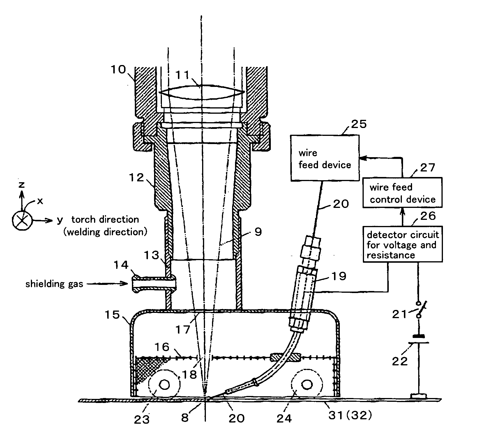
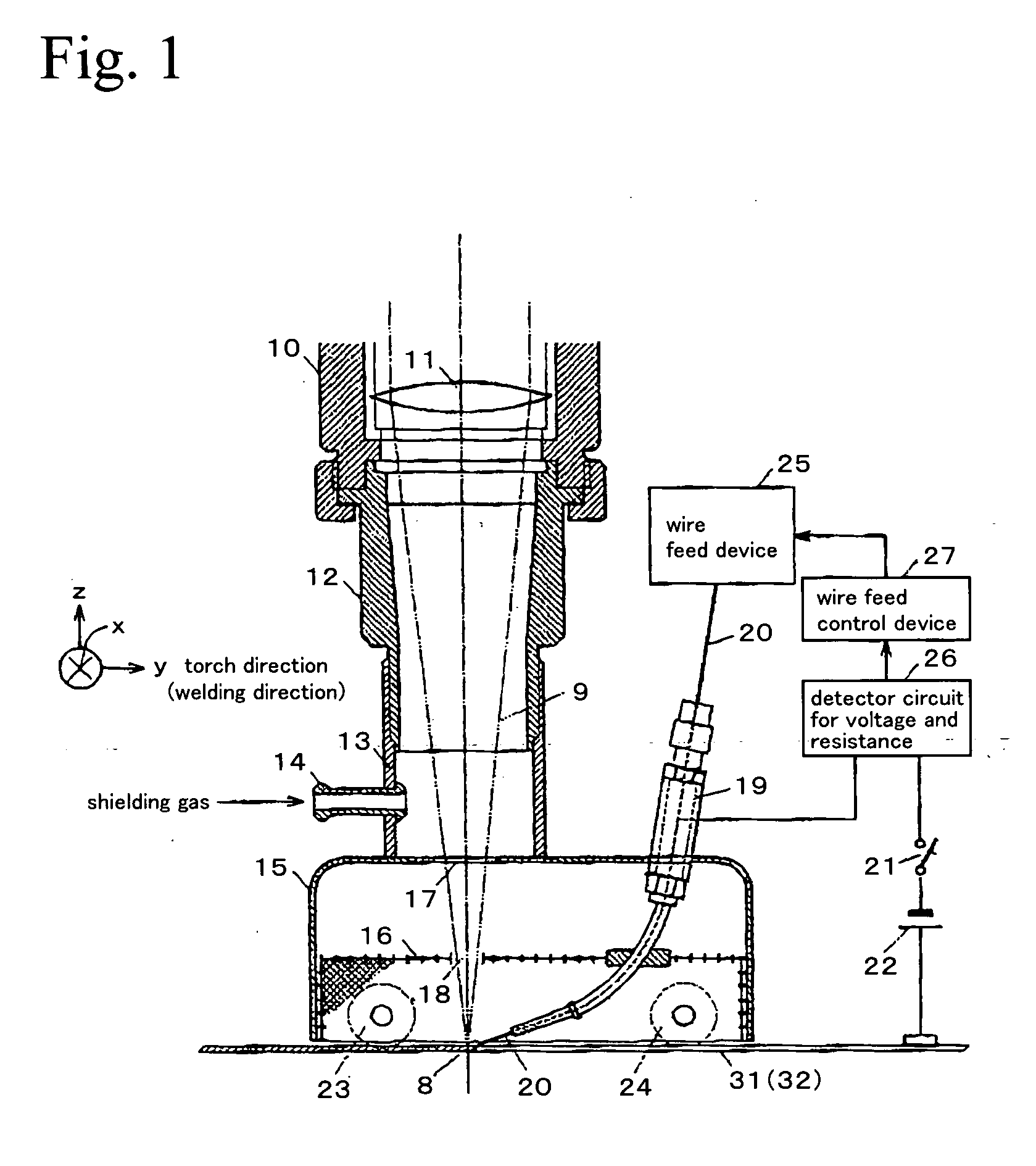
[0037] In a Practical Example of the first embodiment of the present invention, a welding is performed by setting a ratio Vf / V of a feed rate Vf to a welding speed V of the filler wire to be less than 1, that is, setting the feed rate Vf of the filler wire to be less than the welding speed V, resulting in controlling the feed rate Vf of the filler wire to be a rate in which the filler wire does not contact the weld pool. For example, a current value and voltage value between the filler wire and the base materials for welding are detected by a detector circuit (26), whereby a resistance value is calculated. Then, when a ratio Vf / V of a feed rate Vf to a welding speed V of the filler wire is less than 1, when the detected resistance value deviates to a higher value side, the feed rate of the filler wire is increased. On the other hand, when the detected resistance value is deviated to a lower value side, the feed rate of the filler wire is decreased. In this wa...

case 1

(Welding Case 1)

[0050] Base material for welding 31: material A5052, plate thickness 2 mm [0051] Base material for welding 32: material A5052, plate thickness 2 mm, butt joint [0052] YAG laser: output 4 kW, no assist gas (center gas) [0053] Non-load voltage: 20 V, Current: 120 A [0054] Shielding gas: Ar 25 liter / min [0055] Welding speed: 4 m / min, butt joint [0056] Filler wire: standard A5356WY, feed rate: 2 m / min

(Welding Case 2) [0057] Base material for welding 31: material A5052, plate thickness 1 mm [0058] Base material for welding 32: material A5052, plate thickness 1 mm, butt joint [0059] YAG laser: output 3.5 kW, no assist gas (center gas) [0060] Non-load voltage: 20 V, Current: 100 A [0061] Shielding gas: Ar 25 liter / min [0062] Welding speed: 6 m / min, butt joint [0063] Filler wire: standard A5356WY, feed rate: 2 m / min

[0064] As mentioned above, an arc is induced by the plume generated by laser irradiation, whereby arc activation by applying high voltage at a radio-frequency ...

second embodiment

(2) The Second Embodiment

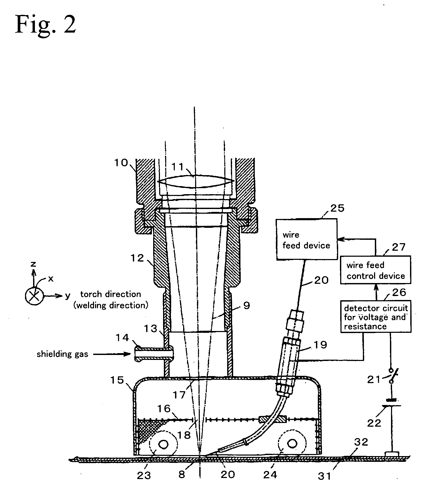
[0065] Moreover, in a Practical Example of the second embodiment of the present invention, the feed rate of the filler wire is controlled, in order to set a ratio Vf / V of a feed rate Vf to a welding speed V of the filler wire to be not less than 1, that is, to set the feed rate Vf of the filler wire to be not less than the welding speed V, thereby controlling the feed rate Vf of the filler wire to be a rate at which the filler wire does not contact the weld pool. For example, current value and voltage value between the filler wire and the base materials for welding are detected, whereby a resistance value between the filler wire and the base materials for welding is calculated. Then, when the detected resistance value deviates to a high value side, feed rate of the filler wire is increased, and when the detected resistance value deviates to a low value side, feed rate of the filler wire is decreased, so as to set the resistance value to be in a setting range...


PUM

PropertyMeasurementUnit
diameteraaaaaaaaaa
diameteraaaaaaaaaa
voltageaaaaaaaaaa

Abstract

A combined welding method with a filler wire using both a YAG laser and an electric arc, and a combined welding device with a filler wire using both a YAG laser and an electric arc, a welding in which a welding gap margin is broad, height and shape of reinforcement of weld, and penetration depth are preferable, can be effectively performed by the method or the device. The welding is performed by directing a laser focus 8 of a YAG laser 9 on base materials 31 and 32 for welding or the vicinity of the focus 8 by a filler wire 20, connecting a power source 22 for applying a voltage to the filler wire between the filler wire 20 and the base materials for welding, irradiating a YAG laser on the base materials for welding in the connecting condition, whereby an arc is induced to the filler wire by a plume (plasma-activated gas and the metal vapor), and holding the plume generated by YAG laser inside and outside of a keyhole.

Description

TECHNICAL FIELD [0001] The invention relates to a combined welding method with a filler wire using both a YAG laser and an electric arc, and relates to combined welding device with a filler wire using both a YAG laser and an electric arc, and specifically relates to a combined welding method with a filler wire using both a YAG laser and an induced arc in which welding is performed using both a YAG laser and an induced arc energy induced at an edge of the filler wire and a combined welding device with a filler wire using both a YAG laser and an induced arc. BACKGROUND ART [0002] YAG laser welding has characteristics mentioned below, and the welding is predominantly used in robot welding of steel materials used for automobiles, etc. [0003] 1. The welding can provide a focused laser, whereby high speed welding with low distortion can be performed. [0004] 2. Laser absorptance of the YAG laser welding is several times of that of CO2 laser welding, whereby efficient welding can be perform...

Claims


Application Information

Patent Timeline
Patent Type & Authority Applications(United States)
IPC IPC(8): B23K9/067B23K9/10B23K9/173B23K26/14
CPCB23K9/0675B23K9/1093B23K26/1429B23K26/203B23K28/02B23K9/173B23K26/211B23K26/348
Inventor SONODA, HIROBUMIOKUYAMA, KENJIIBUKURO, JUNICHIYAHABA, TAKANORITAKIKAWA, MASATOICHIYAMA, YASUTOMOUKENA, TOSHIYASU
Owner HONDA MOTOR CO LTD
Why Eureka
Try Eureka