Display device
a display device and display technology, applied in the field of display devices, can solve problems such as accumulation damage, and achieve the effects of reducing the influence of plasma damage, and small luminance variation
- Summary
- Abstract
- Description
- Claims
- Application Information
AI Technical Summary
Benefits of technology
Problems solved by technology
Method used
Image
Examples
embodiment 1
[Embodiment 1]
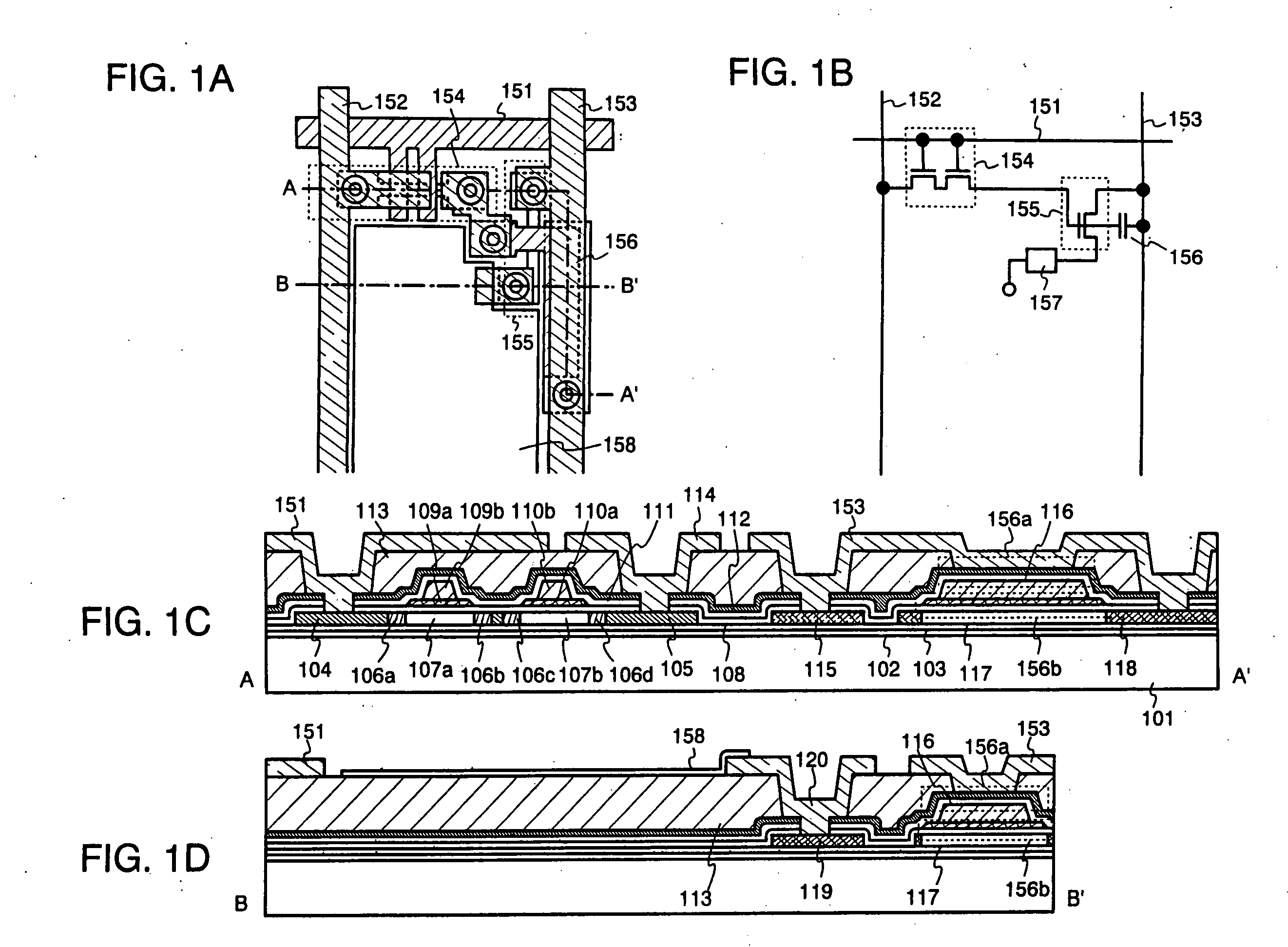
[0245] In this embodiment, an example of an electroluminescence display device of the present invention will be described. FIG. 1A is a top view of a pixel of the electroluminescence display device (note that a state up to the formation of a pixel electrode is indicated), FIG. 1B is a circuit diagram thereof, and FIGS. 1C and 1D each are a cross sectional view along a line A-A′ or B-B′.
[0246] As shown in FIGS. 1A and 1B, a pixel portion of the electroluminescence display device includes a plurality of pixels which are surrounded by gate wirings 151, data wirings 152, and power source wirings (wirings for supplying a constant voltage or a constant current) 153 and arranged in matrix. In each of the pixels, a TFT 154 serving as a switching element (hereinafter referred to as a switching TFT), a TFT 155 serving as means for supplying a current or a voltage for producing light emission of an light emitting element (hereinafter referred to as a driver TFT), a capacitor por...
embodiment 2
[Embodiment 2]
[0264] In this embodiment, description will be given of an example of a device structure including the one in which a planarization layer and a barrier layer are reversed in position in Embodiment 1. Other structures thereof are the same as those in Embodiment 1 and thus, may be attained referring to the description of Embodiment 1. Accordingly, this embodiment will be described focusing on the point different from Embodiment 1.
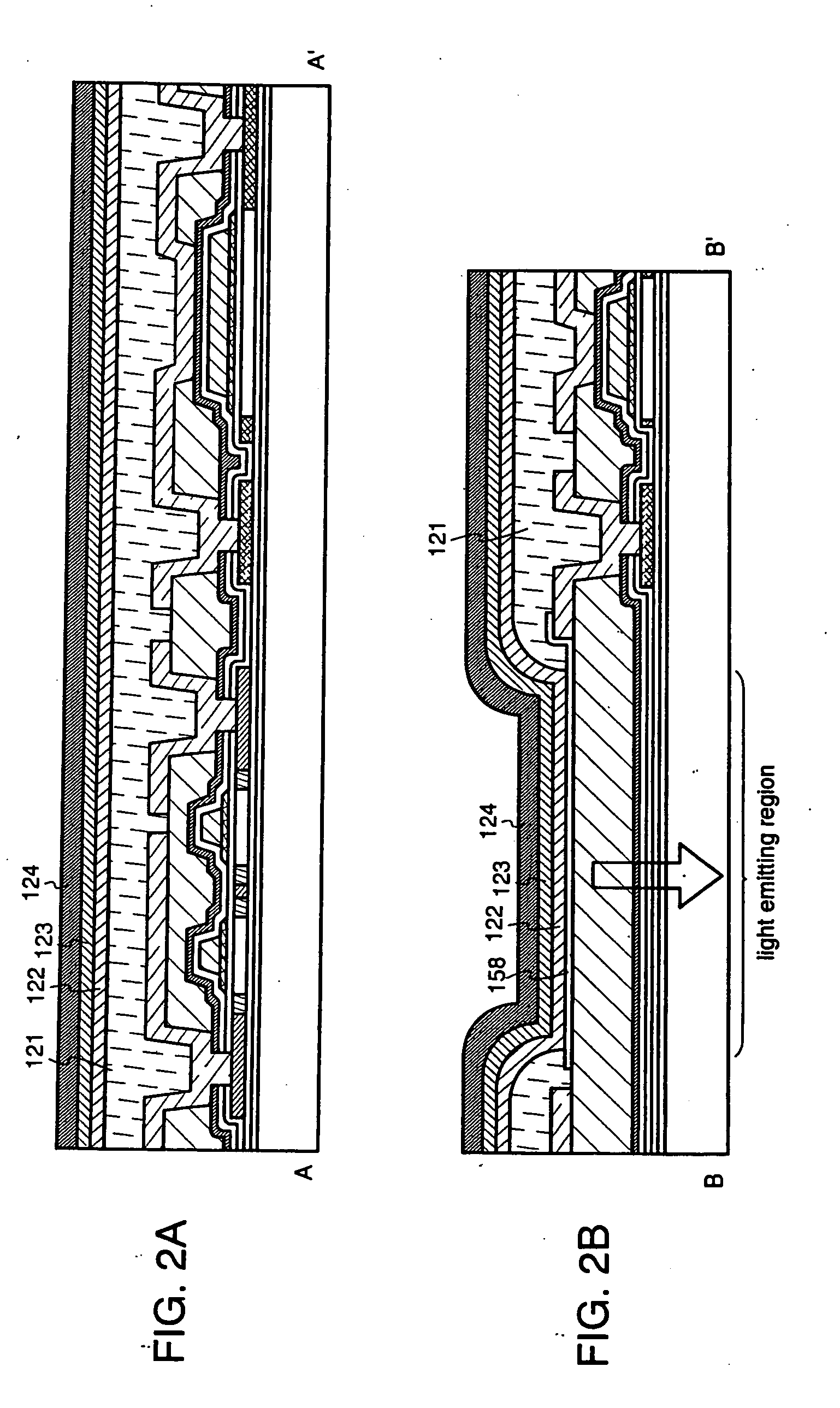
[0265]FIGS. 3A and 3B are views corresponding to FIGS. 2A and 2B in Embodiment 1, respectively. In the figures, some components are denoted by the same reference symbols as those in Embodiment 1. In this embodiment, a planarization layer 301 is formed on an insulating layer 111 and a second opening is formed on the planarization layer 301, after which a barrier layer 302 is formed so as to cover a top surface of the planarization layer 301 and a side surface (inner wall surface) of the second opening. Further, inside the second opening, a gate ...
embodiment 3
[Embodiment 3]
[0267] In this embodiment, description will be given of an example of a device structure including the one in which a planarization layer and a barrier layer are reversed in position in Embodiment 1. Other structures thereof are the same as those in Embodiment 1 and thus, may be attained referring to the description of Embodiment 1. Accordingly, this embodiment will be described focusing on the point different from Embodiment 1.
[0268]FIGS. 4A and 4B are views corresponding to FIGS. 2A and 2B in Embodiment 1, respectively. In the figures, some components are denoted by the same reference symbols as those in Embodiment 1. In this embodiment, a planarization layer 401 is formed on an insulating layer 111 and a barrier layer 402 is formed thereon, after which the barrier layer 302, planarization layer 401, insulating layer 111, and a gate insulating film 108 are etched to form an opening.
[0269] With the structure of this embodiment, degassing from the planarization layer...
PUM
 Abstract
Description
Claims
Application Information
 - R&D
- Intellectual Property
- Life Sciences
- Materials
- Tech Scout
- Unparalleled Data Quality
- Higher Quality Content
- 60% Fewer Hallucinations
Browse by: Latest US Patents, China's latest patents, Technical Efficacy Thesaurus, Application Domain, Technology Topic, Popular Technical Reports.
© 2025 PatSnap. All rights reserved.Legal|Privacy policy|Modern Slavery Act Transparency Statement|Sitemap|About US| Contact US: help@patsnap.com


