
Dilating and support apparatus with disease inhibitors and methods for use

a technology of dilating support and inhibitor, which is applied in the field of medical devices, can solve the problems of multiple balloon devices that are more than complicated, stent deployment requires a significant amount of time for inflation/filling and subsequent deflation/un-filling of balloons, and can only achieve limited success

Inactive Publication Date: 2005-11-10
ARTEMIS MEDICAL
View PDF48 Cites 34 Cited by
  • Summary
  • Abstract
  • Description
  • Claims
  • Application Information

AI Technical Summary

Benefits of technology

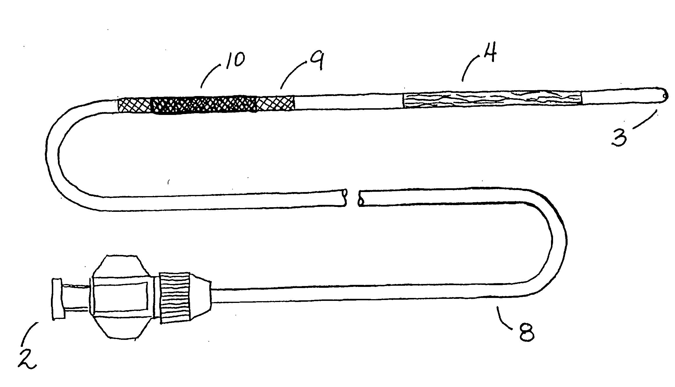
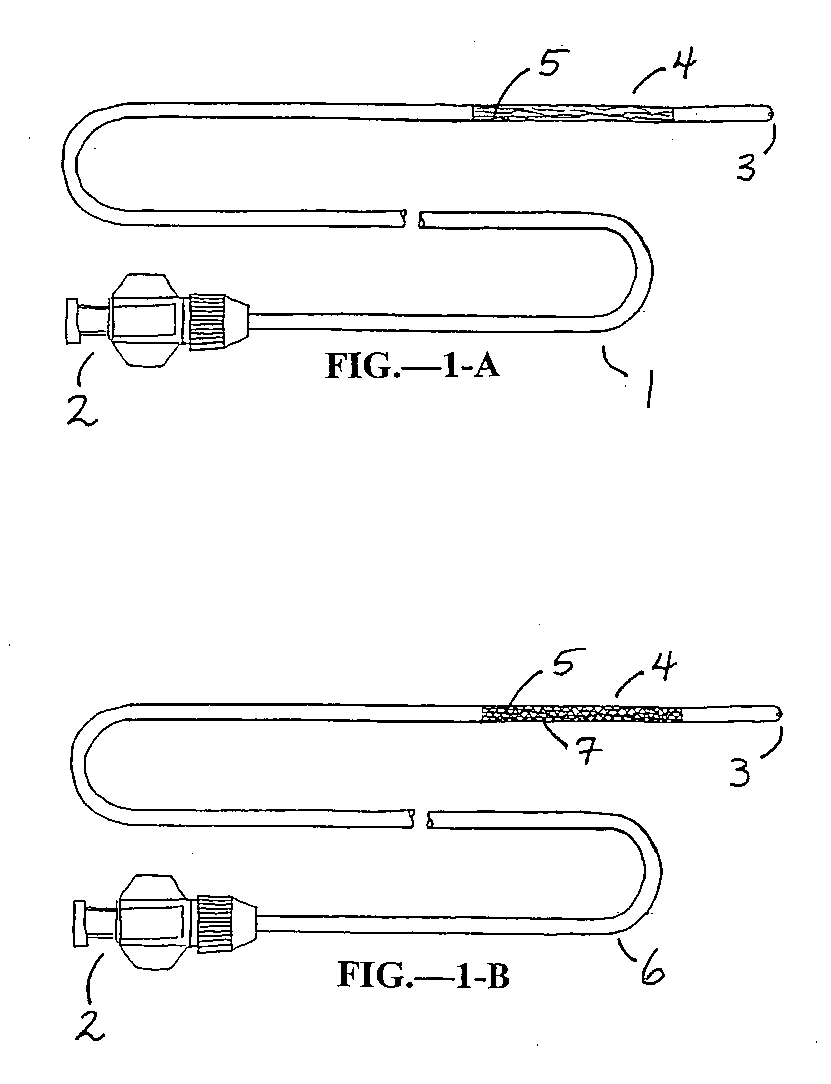
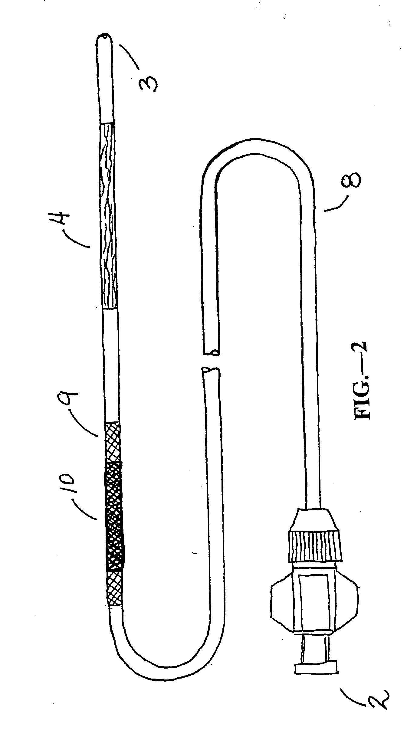
[0033] In a first embodiment of the present invention provides an improved device (guide wire or catheter) of the type having an elongate flexible shaft with a proximal end and a distal end. The improvement comprises configuring at least a distal portion of the flexible shaft so that it can assume a shape(s) along its shaft (proximally, mid-section or distally) that will act as a dilator. This guide wire or catheter can be moved along the lumen (artery, vein, intestine, stent, graft, or other hollow vessel or organ, etc.) and to the obstruction area (clot, plaque, or other obstruction). Once it is in the vicinity of the obstruction / constriction / narrowing, the user (physician / technician) can easily actuate the dilation mechanism(s) so that it is enlarged beyond its original size / diameter and dilate the narrowed passageway. Further, a similar mechanism can be deployed distal to the obstruction so that when the dilatation is occurring and fragments are dislodged during the therapy, the distal mechanism can trap them from moving downstream. These emboli can be trapped and then obliterated or removed at some later time.
[0036] Alternatively, the braid may be constructed of tiny tubular filaments, which may not have absorbent properties. However, because these filaments are tubular in nature, fluids containing drugs or other materials may be injected into them and delivered through them to the vessel wall. It is obvious that a means of injecting fluid into the filaments, such as another lumen in the catheter carrying the device, may be necessary. In addition, the exit site of the tubular filaments could take the form of small holes, porous material, slits, or just weakened areas of the filaments, just to name a few configurations. The tubular design of the filaments of the braid would also add strength to the device so that the outward radial forces needed for scaffolding purposes, described below, would be enhanced.
[0038] Additionally, the aforementioned tubular braided mechanism is easily adapted for use at the exit site for a long term or indwelling catheter or other tube. This exit site is problematic for a variety of reasons; the most important of which is that it is a site when infection can occur. By using the tubular braid with the aforementioned disease inhibiting characteristics, the problems of this ‘exit site’ are greatly reduced. It is a simple matter to manufacture the yarns / strands of the tubular braid using bio-resorbable materials well known to the medical device industry such as, but not limited to de-hydrated collagen strands. These strands readily absorb solvents / solutions- and concurrently could be designed to be reabsorbed by the body in a pre-determined period of time.

Problems solved by technology

Advantages of the LIS approach (over conventional surgery) are significant from a cost as well as a patient care and recovery point of view.
In and of itself, this technique as well as other inventions have tried to accomplish the same, but have been met with limited success.
However, the resulting multiple balloon device is more than complicated and Hegde et al disclose a method for a complex and expensive device.
Further, using balloons for dilatation and for stent deployment require a significant amount of time for inflation / filling and subsequent deflation / un-filling of the balloons.
However, in addition to the inflation and deflation times mentioned above, the device described in this patent has the obvious drawbacks of requiring a separate lumen for each balloon.
In addition to increasing the cost of manufacture, this requirement requires the overall diameter of the catheter to be increased.
Marin and Marin indeed describe an alternative mechanical linkage device for stent deployment in these subsequent patents, however again only at the cost of losing cost effectiveness in the manufacture of the catheter as well as the potential increase in size of the diameters of the catheters and potential flexibility of the catheter / device.
Further, in U.S. Pat. No. 4,585,000, Harold Hershenson describes a mechanical linkage type dilator that is similar to that of Marin and Marin in that it is complicated for manufacture and difficult for size reduction which is of paramount importance.
Further, and again, Gould did not invent the use of the tubular braid in conjunction with other dilation or deployment.
Further, the covering material, such as the tubular braid, will act as a means for penetrating the lesion and potentially breaking up the plaque matrix that exists there.
However, Shockey et al describes a device that is costly and complicated to manufacture.
Klein et al discloses a rather complex device that would lend itself to costly manufacture if it would be put to practice.
The addition of stents to help prevent this re-stenosis has merit and is gaining favor quickly, but does not stop re-stenosis and adds significantly to the treatment costs.

Method used


Image

  • Dilating and support apparatus with disease inhibitors and methods for use
  • Dilating and support apparatus with disease inhibitors and methods for use
  • Dilating and support apparatus with disease inhibitors and methods for use

Examples


Embodiment Construction

[0047] The present invention is used for intervention into the tubular channels (arteries, veins, biliary tract, urological tract, gastrointestinal tract, stents, grafts, sinuses, nasopharynx, heart, ears, etc.) or hollow cavities (stomach, gall bladder, urinary bladder, peritoneum, etc.) of the body. Further, it may be used in iatragenically created passageways. It is particularly convenient to use in an environment of an operating room, surgical suite, interventional suite, Emergency Room, patient's bedside, etc. One preferred embodiment of this device is that the elongate, flexible shaft is inserted into the tubular channel or hollow cavity of the body usually through pecutaneous access or via a surgical incision. In the case of lumens that enter and exit the body naturally, the device may enter through one of those entry or exit paths (i.e. rectal opening, mouth, ear, etc.). Once the device is in the preferred location (that being where the narrowing or obstruction is located), ...


PUM

PropertyMeasurementUnit
Elasticityaaaaaaaaaa
Porosityaaaaaaaaaa
Bioabsorbableaaaaaaaaaa

Abstract

A dilating and support apparatus with disease inhibitors and methods for use is disclosed that is particularly useful for repairing and / or serving as a conduit for body passageways that require reinforcement, dilatation, disease prevention or the like. Such apparatuses are utilized to deliver a therapy, that therapy being from a family of devices, drugs, or any of a variety of other elements to a specific location within the body. The instant disclosure provides a system of combining a novel radial deployment and / or drug delivery therapy with existing balloon dilatation therapy into one device. This combination will yield a significant decrease in cost to the healthcare system as well as providing a therapy to the patient with increased safety and efficacy. Further, the instant invention provides a novel and improved platform for synthetic / tissue interface between the device and the body.

Description

CROSS REFERENCE TO RELATED APPLICATION [0001] The present invention is a continuation of provisional patent applications Ser. No. 60 / 083,178 filed on and claiming priority of Apr. 27, 1998, 60 / 095,106 filed on and claiming priority of Aug. 3, 1998 and 60 / 115,548 filed on and claiming priority of Jan. 12, 1999, the full disclosures of which is incorporated herein by reference. FIELD OF THE INVENTION [0002] The present invention relates to medical devices and their methods of use. More specifically, the present invention relates to devices which are particularly useful for repairing and / or serving as a conduit for body passageways requiring reinforcement, dilatation, disease prevention or the like. Such devices are utilized to deliver a therapy, that therapy being from a family of devices, drugs, or any of a variety of other elements to a specific location within the body. [0003] The present invention provides a system of combining a novel deployment and / or drug delivery therapy with ...

Claims


Application Information

Patent Timeline
IPC IPC(8): A61M37/00A61F2/00A61F2/90A61K9/00A61K31/711A61K51/00A61L29/00A61L29/16A61M25/00
CPCA61F2/90A61F2/958A61F2250/0067A61L29/16A61L2300/258A61L2300/416A61N1/327A61M25/1011A61M25/104A61M2025/0057A61M2025/1052A61M2025/1081A61N1/306A61M25/10
Inventor DUBRUL, WILLIAM RICHARDFULTON, RICHARD E.
Owner ARTEMIS MEDICAL
Learn More