
Quadrature VCO using symmetrical spiral inductors and differential varactors

a spiral inductors and differential varactor technology, applied in the field of quadrature voltage controlled oscillator (vco), can solve problems such as the generation of quadrature local oscillating signals, and achieve the effects of good phase noise, good gain matching, and high phase accuracy

Active Publication Date: 2005-11-17
WINBOND ELECTRONICS CORP
View PDF5 Cites 9 Cited by
  • Summary
  • Abstract
  • Description
  • Claims
  • Application Information

AI Technical Summary

Benefits of technology

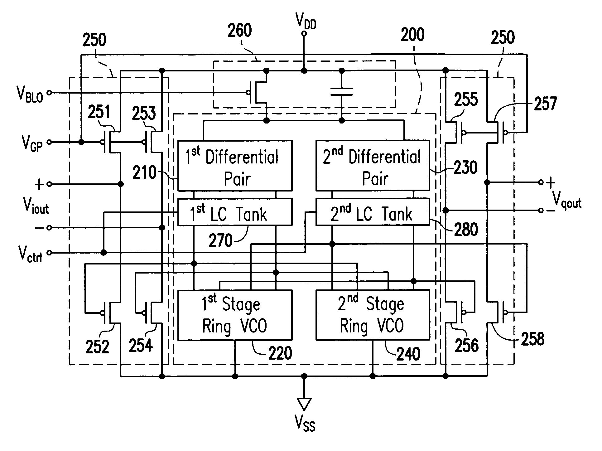
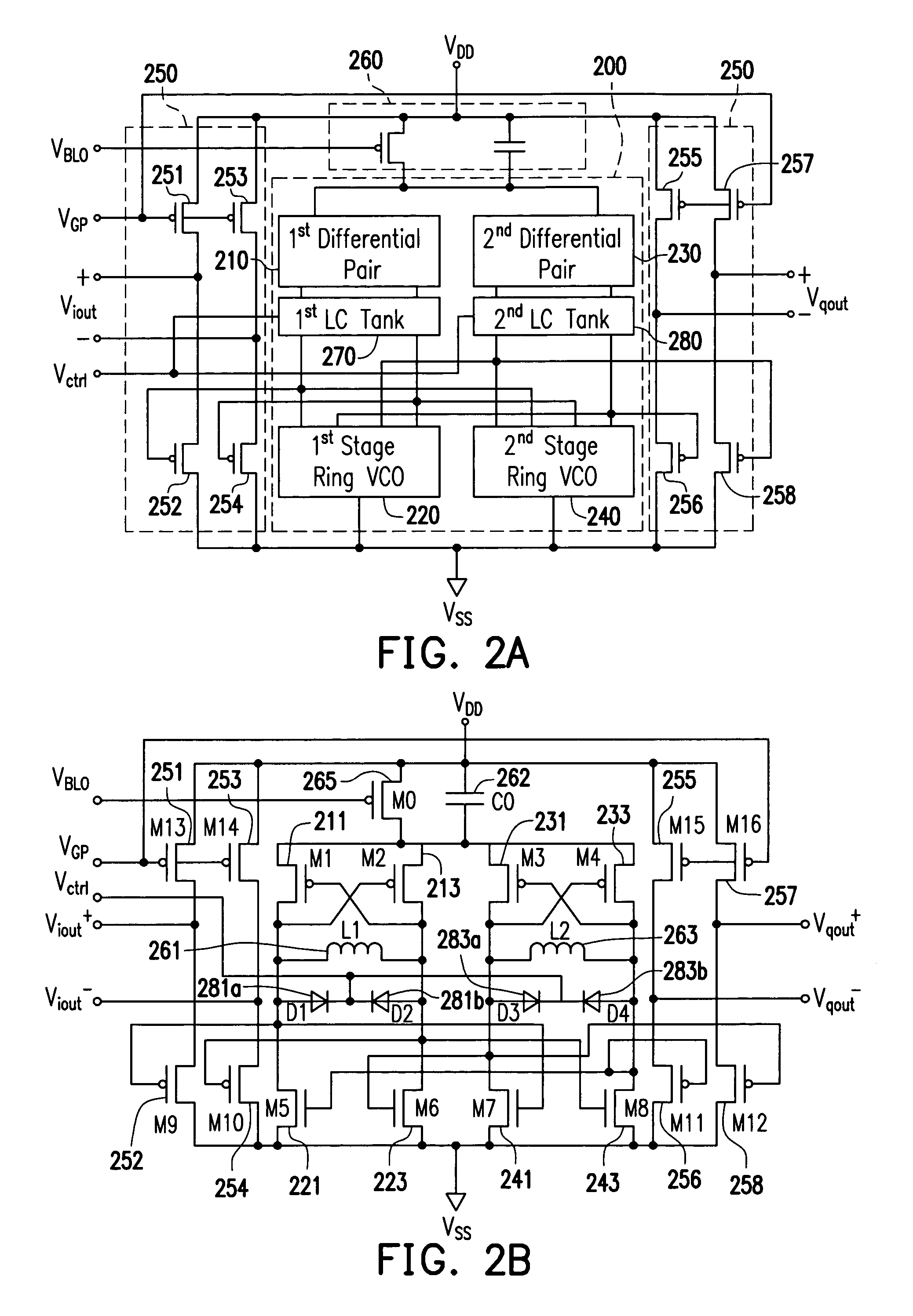
[0012] The quadrature VCO of this present invention includes two pairs of cross-coupled differential pairs. Two LC tanks, playing as oscillating means, are coupled to the differential pairs in series correspondingly. And a two-stage ring oscillator is coupled to the two LC tanks in series in the quadrature VCO of the present invention. A tail current source, implemented with a p-MOSFET for example, and a tail capacitor are coupled in parallel and connected between a voltage source of the quadrature VCO and the differential pair. The tail capacitor is relatively large in capacitance, which provides a low impedance path to ac ground for higher harmonics, so it attenuates the high frequency noise component of the tail current source and improves the phase noise performance of the whole VCO. The cross-coupled differential pairs, implemented with p-type transistors, particularly p-MOSTFETs for example, in positive feedback, feed the LC tanks to compensate the loss.
[0014] Wherein the LC tanks is based on on-chip symmetrical spiral inductors and differential varactors. In CMOS fabrication technology, for example, the inductor is mainly wound with the top metal layer, but the crossover sections include the next top metal layer over a substrate. On the other hand, the differential varactor is realized as reverse-biased differential diodes. The path to the small-signal ground can still be shorted if devices in the differential varactor with opposite polarity alternate for symmetry reason. These differential structures improve the tank's quality factor, and the symmetry of the circuit, all these will lower flicker noise up-conversion. Moreover, the differential LC tank reduces the chip area consumed by the LC tank since a LC tank in this present invention is only consisted of a symmetrical spiral inductor and a differential varactor.
[0015] The two-stage differential ring oscillator comprises n-MOSFETs, for example. The outputs of each stage are 90° out of phase. By combination of the ring oscillator and local oscillator, the low phase noise quadrature LO signals are obtained. The tail current source, which is also a constant current source, shared by the two sections, further enhance the accuracy of the quadrature VCO.
[0017] According to the circuitry in this present invention, a 2.4 GHz quadrature VCO with symmetrical spiral inductors and differential varactors is provided. It can generate quadrature LO signals with high phase accuracy and good gain matching under low power, good phase noise and small chip area, thus it can be applied to a variety of integrated transceivers.

Problems solved by technology

In the design of these transceiver systems, a major challenge is the generation of quadrature local oscillating (LO) signals.

Method used


Image

  • Quadrature VCO using symmetrical spiral inductors and differential varactors
  • Quadrature VCO using symmetrical spiral inductors and differential varactors
  • Quadrature VCO using symmetrical spiral inductors and differential varactors

Examples


Embodiment Construction

[0029] Referring to FIG. 2A, a schematic block diagram of VCO circuitry according to an embodiment of the present invention is illustrated herein. The VCO circuitry includes an oscillating unit 200, a source unit 260, and a source follower unit 250. Wherein the oscillating units includes two identical sets of the following structure: a first differential pair 210 coupled to a first LC tank 270 and a first ring VCO 220 in series between power supply and ground in the circuitry of the present invention, and a second set of devices is coupled in an identical fashion as that of the first set of devices described above. The source unit 260 includes a tail current source 265 and a tail capacitor 262 coupled in parallel between the voltage supply VDD and a first node. The tail current source 265, controlled by a voltage level VBLO, comprises a p-type transistor, a p-MOSFET for example. The tail capacitor 262 is relatively large in area for providing stable current source. Furthermore, the ...


PUM


Abstract

A quadrature VCO includes two cross-coupled differential pairs, two parallel LC tank circuits, two LO units and a plurality of source followers, supplying by a tail current source and a tail capacitor. The LC tank circuit constitutes of symmetrical spiral inductors and differential varactors, which constitutes of common anode diodes. The quadrature VCO circuitry is implemented on a chip with 2.4 GHz operating frequency. The quadrature VCO generates quadrature LO signals with high phase accuracy and good gain match under low power, good phase noise and small chip area, thus it can be applied to a variety of integrated transceivers.

Description

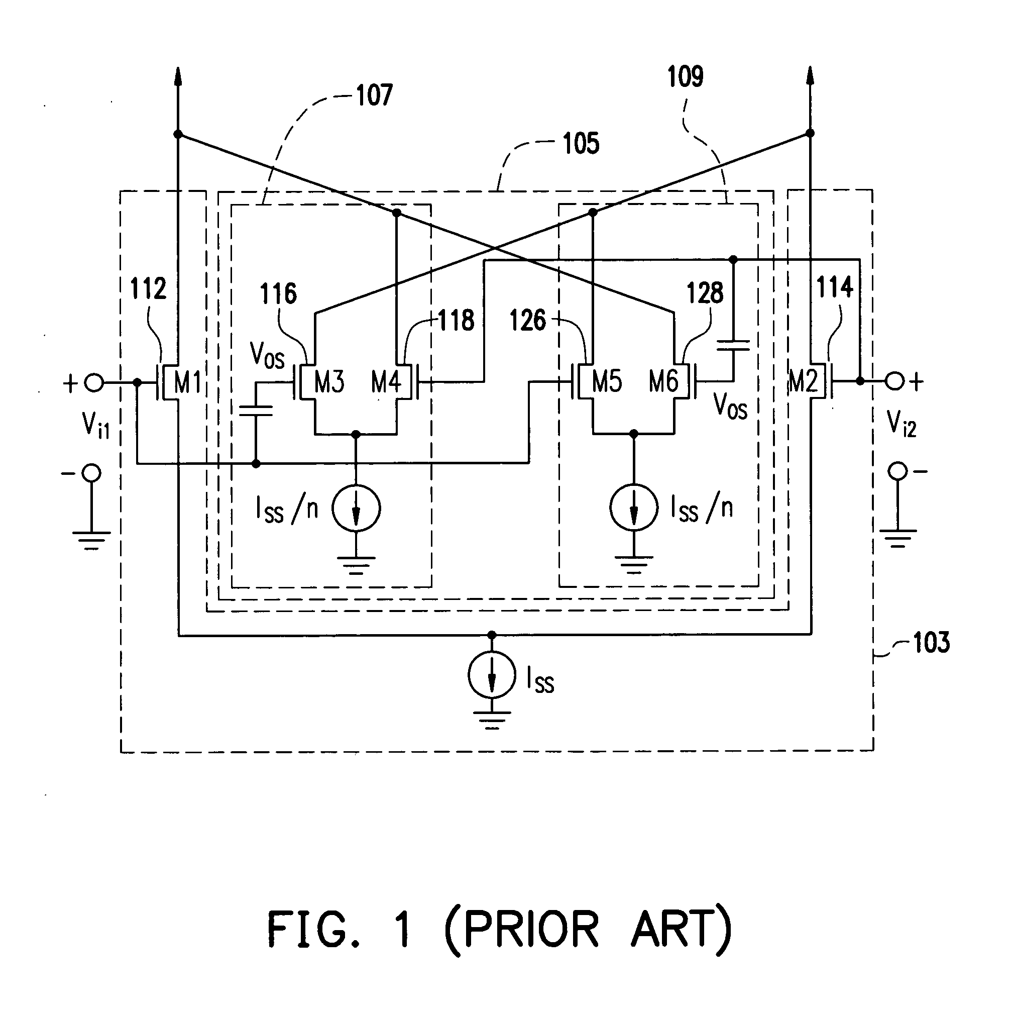
BACKGROUND OF THE INVENTION [0001] 1. Field of Invention [0002] The present invention relates to a quadrature voltage controlled oscillator (VCO), and more particularly, to a quadrature VCO circuitry with symmetrical spiral inductors and differential varactors implemented with complementary MOS in a system on chip. [0003] 2. Description of the Related Art [0004] Voltage controlled oscillator (VCO) is widely used, for example in many transceivers incorporate quadrature downconverions mixers. Applications can include broadcast receivers such as radio and television, set top boxes for cable television, receivers in local area networks, test and measurement equipment, radar receivers, air traffic control receivers, and microwave communication links, etc. In the design of these transceiver systems, a major challenge is the generation of quadrature local oscillating (LO) signals. [0005] Referring to FIG. 1, a differential pair incorporating two auxiliary cross-coupled differential pairs i...

Claims


Application Information

Patent Timeline
IPC IPC(8): H03B1/00H03B5/12H03B27/00
CPCH03B27/00H03B2201/0208H03B5/1293H03B5/1215H03B5/1243H03B5/1228
Inventor SHI, BINGXUECHI, BAOYONG
Owner WINBOND ELECTRONICS CORP
Learn More