Method and arrangement for the plasma-based generation of intensive short-wavelength radiation

a plasma-based and short-wavelength radiation technology, applied in the direction of x-ray tubes, nuclear reactors, x-ray tubes with very high current, etc., can solve the problems of not being able to use xenon to generate individual droplets under the process conditions, not being able to achieve the effect of reducing the emission of debris

Inactive Publication Date: 2005-11-24
XTREME TECH
View PDF10 Cites 22 Cited by
  • Summary
  • Abstract
  • Description
  • Claims
  • Application Information

AI Technical Summary

Benefits of technology

[0009] It is the primary object of the invention to find a novel possibility for plasma-based generation of intensive short-wavelength radiation, particularly soft x-radiation, which permits efficient energy conversion in a desired spectral band with high repetition frequency (several kHz) of the plasma excitation, minimized emission of debris and low erosion of the nozzle of the target generator.
[0021] In order to minimize the return of hydrodynamic disturbance (shock waves due to the generation of the hot plasma at the interaction point) into the continuous target flow and / or to improve the conversion efficiency of desired emitted radiation in the hot plasma, a synchronizing device is provided for adjusting the time position of the pulses of the high-energy beam and dividing beam (additional energy beam). The synchronizing device has a trigger unit and / or a delay element for synchronizing two separate energy beam sources for the high-energy beam and the additional energy beam. The delay element can be an optical or electronic delay loop. When a portion is to be coupled out of the high-energy beam for the dividing beam, the synchronizing device advantageously has a delay element in only one of the beam paths of the high-energy beam or dividing beam.
[0023] The invention resolves this conflict in that in order to provide the target in a highly repetitive manner the energy pulse generating the radiating plasma impinges on a target volume that is decoupled from the target volume flowing after it by a separation process that takes place ahead of it spatially (division or at least spatially limited thinning of the continuous target flow over the entire target diameter). By means of a small (compared to the high-energy pulse) introduction of energy, the hydrodynamic disturbances caused by the radiation-generating energy pulse cannot propagate in the subsequently flowing target volume or is at least greatly attenuated. The resulting advantages are potentially high pulse repetition frequencies and—in contrast to conventional droplet generation—a volume that can be adjusted relatively simply over the length of the decoupled target portion which results in low debris emission by way of a mass-limited target. Further, the synchronization of the separating process with the radiation-generating energy pulse is also substantially simpler than in “natural” droplet formation in which the droplet frequency is not completely free from fluctuations.
[0024] Moreover, due to the low divergence of the target flow that is initially provided in a continuous manner (jet), a relatively large working distance from the nozzle can be selected (order of magnitude of several centimeters). Accordingly, in conjunction with the inventive separation of the continuous target flow, the erosion of the nozzle of the target generator and the thermal loading per unit of area are reduced.
[0025] The invention makes it possible to realize a radiation source with a high average output based on a plasma for generating an intensive short-wavelength radiation which permits an efficient energy conversion (with excitation pulse energies of some 10 mJ) in a desired spectral band and a high repetition frequency (several kHz) of the plasma excitation with a liquid target flow that is provided in a reproducible manner. This appreciably reduces erosion of the target nozzle and / or emission of debris.

Problems solved by technology

However, the generation of droplets in a vacuum chamber depends upon the characteristics of the target material and is not possible for every target material.
For example, xenon cannot be used to generate individual droplets under the process conditions of EUV lithography.
Therefore, the energy beam can be coupled in efficiently only in the immediate vicinity of the nozzle, which leads to a high thermal loading of the nozzle and inevitably results in nozzle erosion.
While arrangements with a continuous target jet (liquid or frozen jet) such as is described in WO97 / 40650, for example, allow a relatively large working distance from the nozzle, they are susceptible to shock waves.
This means that the radiation-generating energy pulse that is coupled in causes hydrodynamic disturbances extending relatively far along the jet axis and the characteristics of the continuing jet for optimal plasma generation and radiation generation are impaired.

Method used


Image

  • Method and arrangement for the plasma-based generation of intensive short-wavelength radiation
  • Method and arrangement for the plasma-based generation of intensive short-wavelength radiation
  • Method and arrangement for the plasma-based generation of intensive short-wavelength radiation

Examples


example 1

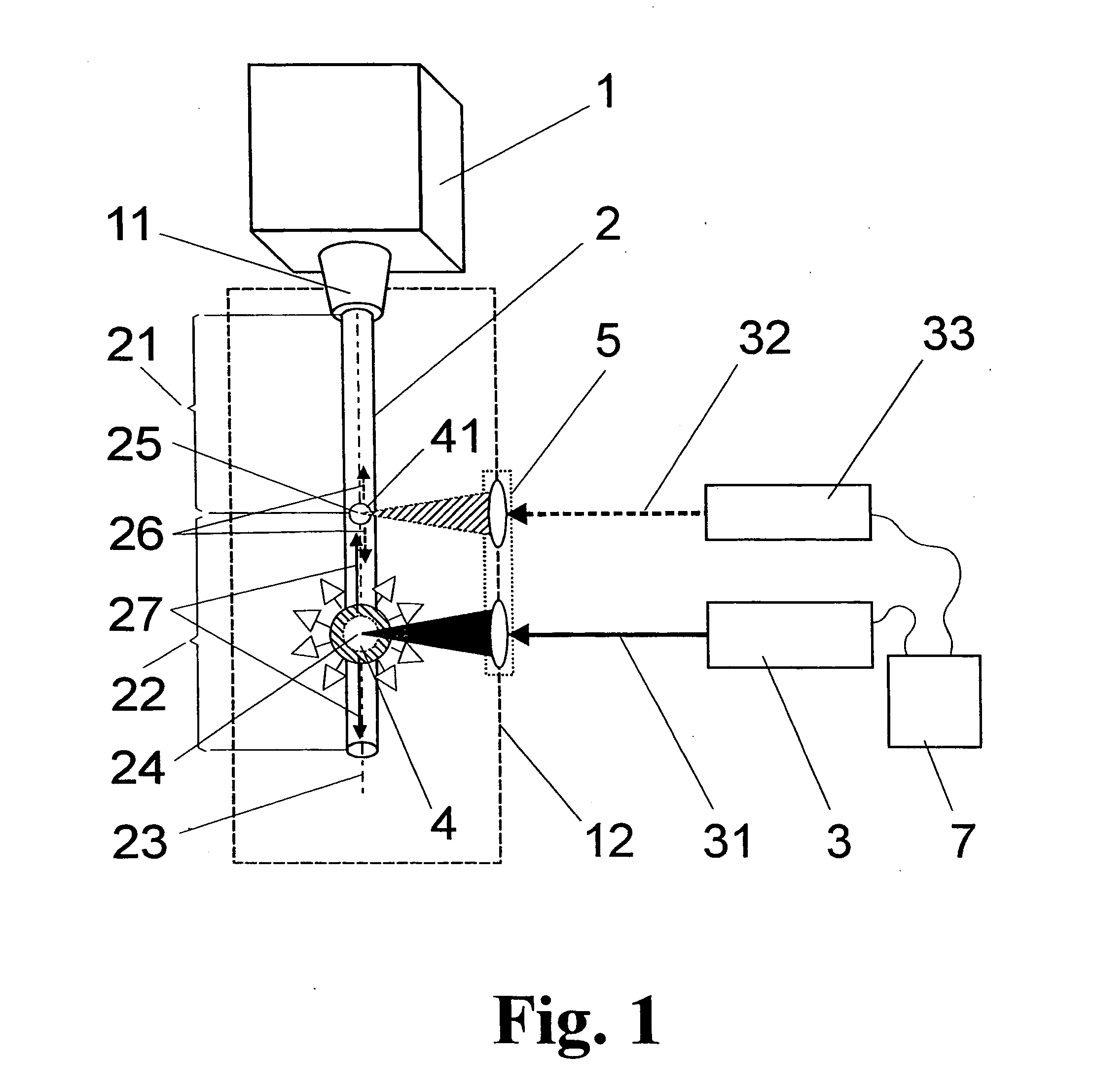
[0063]FIG. 3 is based on the diagram in FIG. 2 in that a polarized laser beam enters a beam guiding device 6, where it is converted by a half-wave plate 61 into a laser beam with nonvanishing orthogonal polarization components and is divided by means of a polarizing beam splitter 62 into different portions with polarization vectors ∥ and ⊥, respectively, that are parallel to or perpendicular to the drawing plane.

[0064] The laser beam with the parallel polarization vector ∥ arrives at the focusing lens 51 via a deflecting mirror 63 and a polarizing splitter 64 for this polarization direction located in the passing direction.

[0065] The laser beam with the perpendicular polarization vector ⊥ is directed by a tilting mirror 65 to a retroreflector 66 which reflects in parallel the beam deflected by the tilting mirror 65 and directs it to the polarizing splitter 64. The beam path along the tilting mirror 65 and the retroreflector 66 to the splitter 64 is an optical delay element 72 by w...

example 2

[0067] In the variant according to FIG. 4, the excitation laser beam 34 and dividing laser beam 35 are generated in two triggered lasers, laser A and laser B. The trigger unit 71 provided for this purpose normally triggers both lasers A and B simultaneously so that a delay element, which is realized in this case as an optical delay element 72 as in FIG. 3, is required for adjusting a time shift of the laser pulses. However, controlling by means of offset trigger pulses from the trigger unit 71 is also possible.

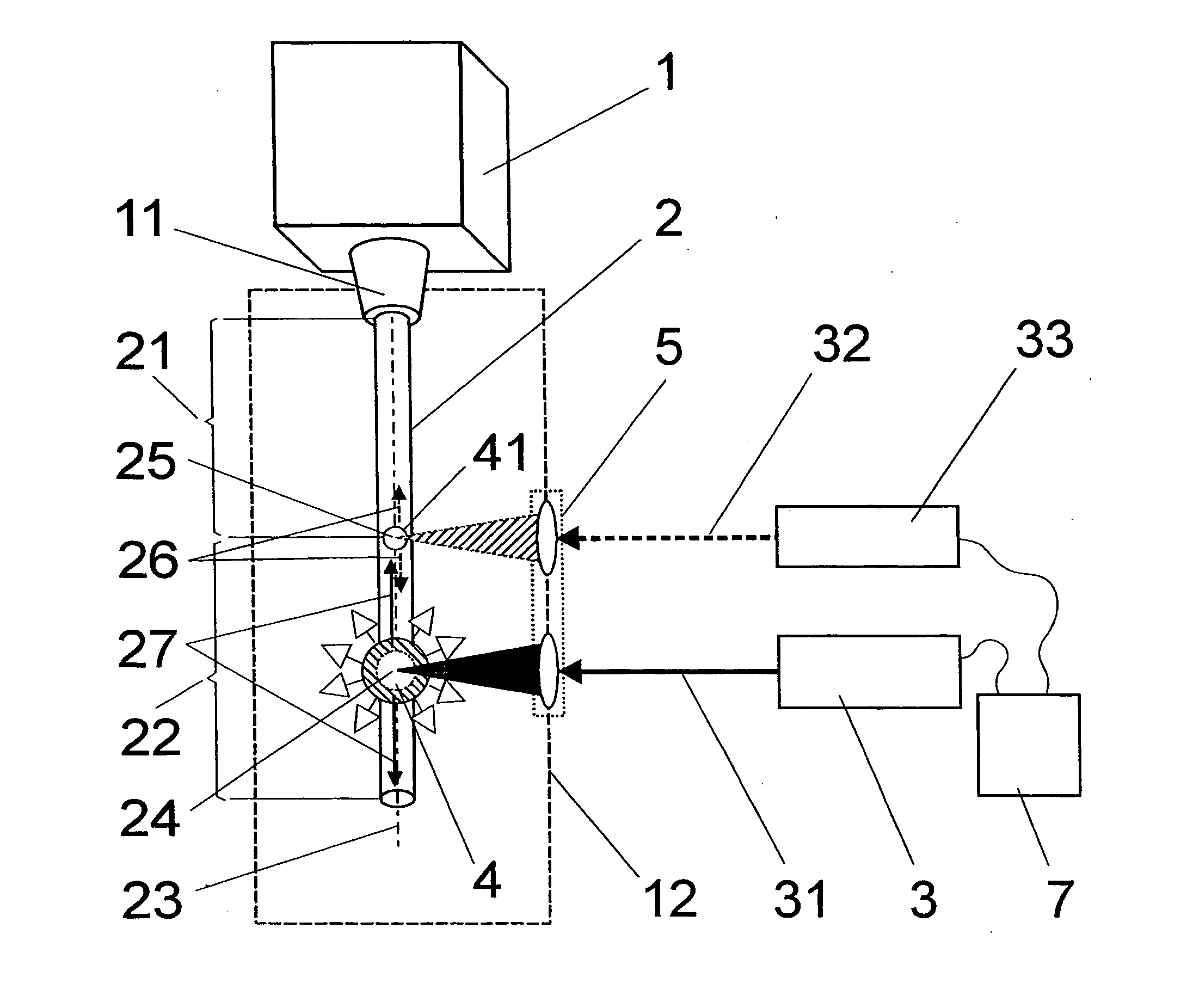
[0068] In this example and in all of the following examples, the portions 22 that are divided (not necessarily completely) from the continuous target jet 21 are generated in that the beam bundles 52 and 53 focused by the lasers A and B are focused on different locations (located one after the other along the target axis 23) which—assuming a target diameter of 20 μm—lie at a distance from one another of some 10 μm to several millimeters or in special cases (as is described lat...

example 3

[0071] In the arrangement shown in FIG. 5, two lasers A and B which are polarized linearly orthogonal to one another are combined by a polarizing splitter 64. The beam bundles 52 and 53 striking the focusing lens 51 are tilted slightly with respect to one another. The inclination of the beam axis directed to the splitter 64 is adjusted by the tilting mirror 65. As is described with reference to FIG. 4, a time delay of the pulses of the two lasers A and B, which is again optional, is realized by optical means by an additional retroreflector 66. In this example, the adjustment of the pulse delay of laser A is again carried out by means of a movable retroreflector 65, but could be realized alternatively in the same way in the beam path of laser B.

[0072] When using two lasers A and B with different wavelengths, the beam splitter 64—in contrast to the principle shown in FIG. 5—can also be realized as an edge filter (dichroic mirror) for combining the two laser beams with a slight tilt r...


PUM

PropertyMeasurementUnit
repetition frequenciesaaaaaaaaaa
wavelengthaaaaaaaaaa
diameteraaaaaaaaaa

Abstract

The invention is directed to a method and an arrangement for the plasma-based generation of intensive short-wavelength radiation, particularly EUV radiation. The object of the invention, to find a novel possibility for plasma-based generation of intensive soft x-radiation, particularly EUV radiation, which permits efficient energy conversion in the desired spectral band with high repetition frequency (several kHz) of the plasma excitation, minimized emission of debris and low erosion of the nozzle of the target generator, is met according to the invention in that an additional energy beam is directed on the target flow spatially in advance of its interaction with the high-energy beam, the target flow being acted upon by this additional energy beam with substantially weaker energy pulses compared to the high-energy beam in order to divide the target flow into a first portion and at least one second portion, wherein the target flow is excited at an interaction point within the second portion by the high-energy beam for generating a hot, radiating plasma, and the second portion is decoupled from the first portion and therefore from the target generator in such a way that a hydrodynamic disturbance generated in the second portion by the pulse of the high-energy beam is transmitted into the first portion only negligibly.

Description

CROSS-REFERENCE TO RELATED APPLICATIONS [0001] This application claims priority of German Application No. 10 2004 005 242.5, filed Jan. 30, 2004, the complete disclosure of which is hereby incorporated by reference. BACKGROUND OF THE INVENTION [0002] a) Field of the Invention [0003] The invention is directed to a method and an arrangement for plasma-based generation of intensive short-wavelength radiation in which a target flow comprising defined portions which is made available in a reproducible manner interacts with a pulsed energy beam for exciting radiation-emitting plasma. The invention is particularly suitable for the generation of soft x-radiation, preferably EUV radiation, for the exposure of very small structures in semiconductor lithography. [0004] b) Description of the Related Art [0005] In the prior art relating to energy beam pumped plasma-based radiation sources, mass-limited targets for plasma generation have become increasingly accepted because they minimize unwanted...

Claims


Application Information

Patent Timeline
Patent Type & Authority Applications(United States)
IPC IPC(8): G21K5/08G03F7/20G21B1/00H01L21/027H05G2/00
CPCH05G2/008H05G2/003Y02E30/10
Inventor GAEBEL, KAIZIENER, CHRISTIANHERGENHAN, GUIDO
Owner XTREME TECH
Why Eureka
Try Eureka