

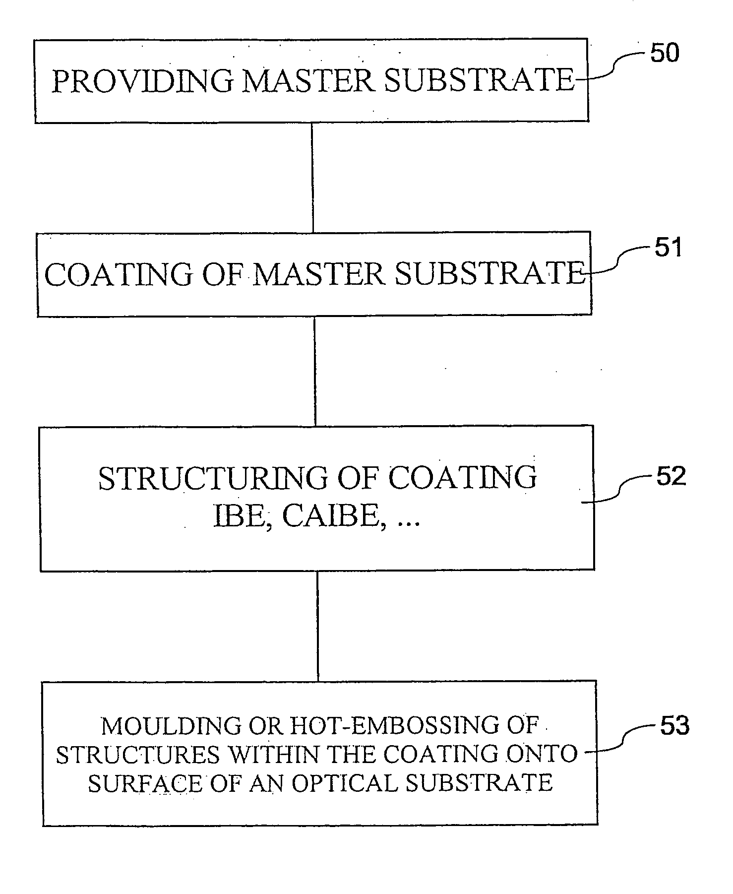
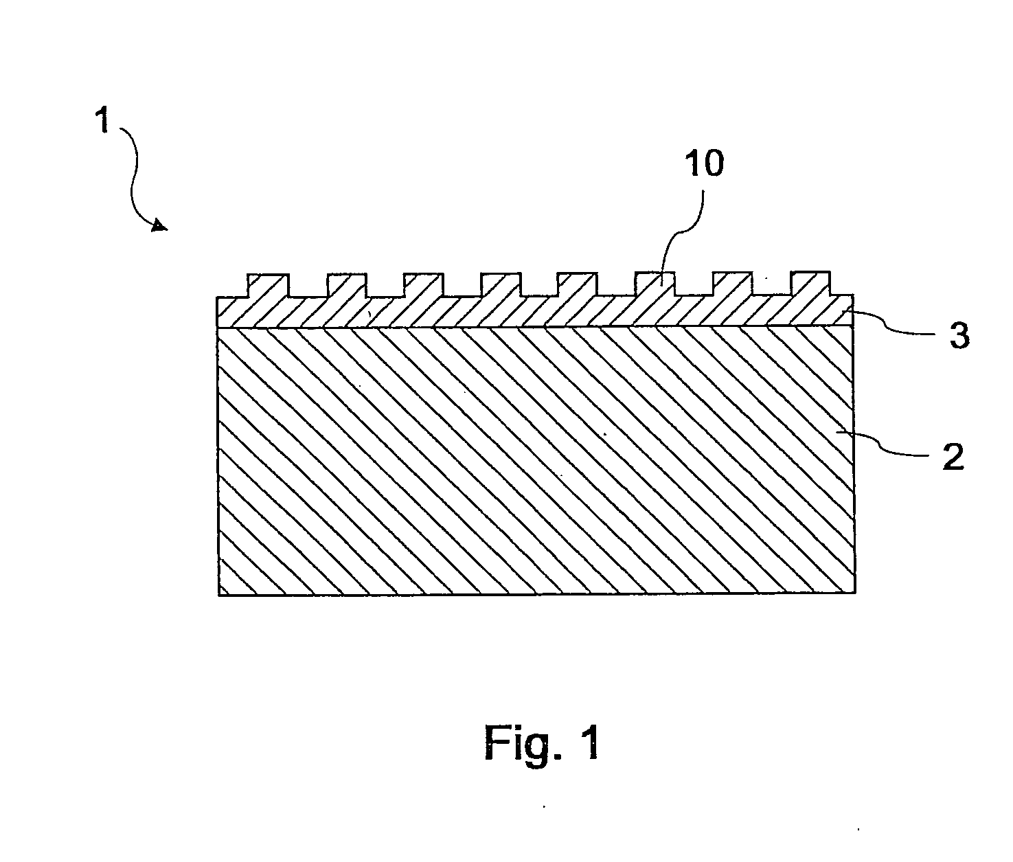
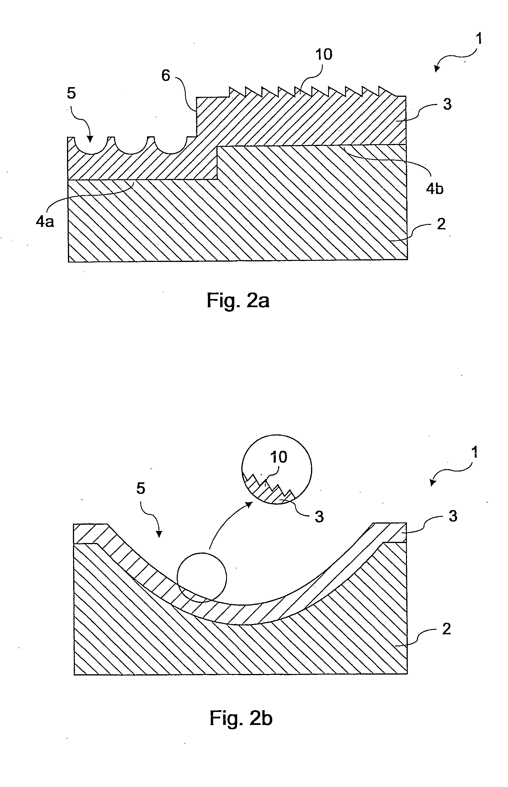
Method for manufacturing a master, master, method for manufacturing optical elements and optical element
a manufacturing method and technology for optical elements, applied in the field of manufacturing optical elements, can solve the problems of affecting the service life of the master and its precision, affecting the accuracy of the moulding or hot embossing process, and the material of the optical substrate tending to adhere to the master during the demoulding process, so as to achieve the effect of reducing the cost of manufacturing
- Summary
- Abstract
- Description
- Claims
- Application Information
AI Technical Summary
Benefits of technology
Problems solved by technology
Method used
Image

Examples
embodiment 1
[0066] A layer of Al2O3 with a thickness of 2000 nm was formed on a substrate of steel by means of ion beam deposition (IBD) of Al2O3. A Kaufmann source was used for the ion beam deposition. The working gas used for the ion beam consisted of argon (Ar), and the sputtering time was 106 min.
[0067] The Al2O3 coating formed on the substrate was structured by means of reactive ion etching (RIE) in a system of the type Vacutec 500. A gas flow of CF4 (47 sccm) was used as the etching gas, and the working pressure amounted to approximately 160 mTorr. A chrome layer was applied as the etching mask before the etching process.
[0068] Groove-shaped structures for moulding or hot embossing a diffraction grating were produced in the Al2O3 coating by means of reactive ion etching. The maximum etching depth was 420 nm. A microscopic investigation with a magnification ×400 showed that no visible material removal took place in the Cr layer. Cr consequently can be used as a stable masking layer for t...
embodiment 2
[0069] A chrome layer (Cr) with a thickness of 100 nm was produced on a substrate of steel by means of DC magnetron sputtering. Chrome with a diameter of 3 inches and a purity of 99.99 (4N) was used as the target. The gas used during the sputtering process consisted of argon 5.0, and the pressure during the coating process amounted to approximately 7.5×10⁻⁴ Torr. The coating time amounted to approximately 200 s.
[0070] A photoresist layer applied on the Cr coating was then exposed with a screen pattern in a photolithographic process. Unexposed photoresist layer sections were rinsed off. The thusly produced Cr coating on the substrate was manually etched in a wet-chemical process in a beaker under clean room conditions. An etching solution of K3Fe(CN)6 and NaOH was used. The temperature during the etching process was 50° C. The coating was rinsed with DI water for approximately 60 s after the etching process, and the substrate was subsequently dried by means of centrifuging for 40 s ...
embodiment 3
[0072] A layer of ZrO2 with a thickness of 2000 nm was produced on a substrate of steel by means of ion beam deposition (IBD) of ZrO2. A Kaufmann source was used for the ion beam deposition. The working gas for the ion beam consisted of argon (Ar), and the sputtering time amounted to approximately 138 min.
[0073] The ZrO2 coating produced on the substrate was structured by means of ion beam etching (IBE). A Kaufmann source was used for this purpose, and the working gas for the ion beam consisted of Ar with a working pressure of 3.2×10⁻⁴ mbar. A chrome layer with a thickness of 100 nm was applied as a masking layer and subsequently structured by exposing an AZ 5214 E photoresist (thickness: 1400 nm).
[0074] Groove-shaped structures for moulding or hot embossing a diffraction grating were formed within the ZrO2 coating by means of reactive ion etching. The maximum etching depth amounted to 600 nm. A microscopic investigation with a magnification ×400 showed that no visible material re...
PUM
| Property | Measurement | Unit |
|---|---|---|
| height | aaaaa | aaaaa |
| temperatures | aaaaa | aaaaa |
| thickness | aaaaa | aaaaa |
Abstract
Description
Claims
Application Information