Embolization device for vessel cavity in vivo

a technology of abolization device and a cavity, which is applied in the field of embolisation device, can solve the problems of infection, difficult to perform such a surgical procedure, and difficulty in performing such a clipping treatmen

Inactive Publication Date: 2005-12-01
KANEKA CORP
View PDF10 Cites 7 Cited by
  • Summary
  • Abstract
  • Description
  • Claims
  • Application Information

AI Technical Summary

Benefits of technology

[0022] In addition, the embolization device is preferably a coil. More preferably, the coil comprises a metal wire composed of any one of platinum, gold, silver, and tantalum, or an alloy wire containing any one of platinum, gold, silver, and tantalum in an amount of 80% by weight or more.

Problems solved by technology

However, in the case of high severity, such as deep coma or unstable blood pressure, it is difficult to perform such clipping treatment.
Furthermore, clipping is an invasive treatment requiring a craniotomy, and infection associated, with the craniotomy is a problem.
Moreover, since direct surgery is performed in the clipping treatment, depending on the site of the cerebral aneurysm, there may be a case in which it is difficult to perform a surgical procedure, which is also a problem.
Therefore, the coil embolization can be applied in cases of high severity to which clipping treatment is not applicable and to elderly people.
However, coil embolization is not applicable to the treatment of all ruptured cerebral aneurysms because of its specific problems.
For example, when coil embolization is used in a cerebral aneurysm with a large diameter, it is difficult to completely embolize the aneurysm, and compaction of the indwelling embolization coil (coil compaction) easily occurs after treatment, resulting in a high possibility of rebleeding.
Furthermore, in the case of a cerebral aneurysm with a wide neck 2 (refer to FIG. 1), the indwelling embolization coil is easily dislodged from the aneurysm to a parent blood vessel 3 (refer to FIG. 1), and it has been pointed out that there is a possibility of complications, such as cerebral infarction, being caused because the thrombi formed on the surface of the dislodged embolization coil flow to peripheries through the bloodstream.
Moreover, in the case of a cerebral aneurysm which is formed in a branch of a blood vessel, there is a risk of occlusion in the branch.
As described above, although coil embolization is a less invasive treatment, the shape of a cerebral aneurysm for which the coil embolization can be used is limited, and the coil embolization is not yet a technique that is superior to clipping treatment.
Platinum, which is a material mainly constituting the embolization coils currently in use, is extremely inactive in vivo, and therefore, fibrous tissue formation (organization) does not easily take place in cerebral aneurysms treated with coil embolization.
This fact has been pointed out as a limiting factor in the application of coil embolization.
However, attachment of a fibrous member to an embolization coil gives rise to problems.
For example, the fabrication process becomes complex.
Furthermore, since it is difficult to view the fibrous member by X-ray fluoroscopy, there is a possibility that the fibrous member may be dislodged into a parent blood vessel, resulting in complications, such as cerebral infarction.
However, the biocompatible polymers disclosed are fibrous materials with thrombus-forming properties, and it is evident that there is a possibility of the same problems occurring as those described above.
However, since the strand that can be placed in the embolization coil has an extremely small diameter, it is difficult to produce such a strand.
Furthermore, the flexibility of the entire embolization coil is inevitably decreased because of the placement of the strand, and thus there is an unavoidable possibility of causing serious complications, such as perforation of the aneurysm during the placement of the embolization coil.

Method used


Image

  • Embolization device for vessel cavity in vivo
  • Embolization device for vessel cavity in vivo
  • Embolization device for vessel cavity in vivo

Examples


example 1

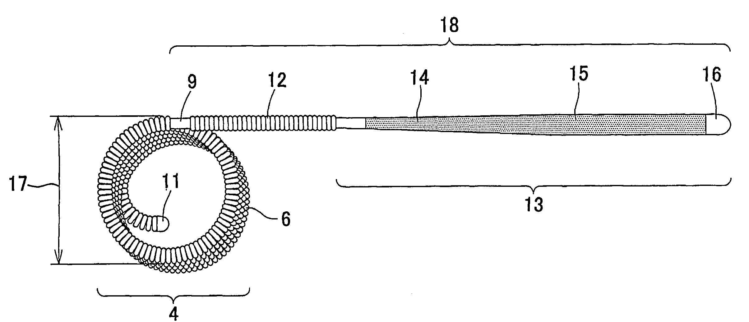
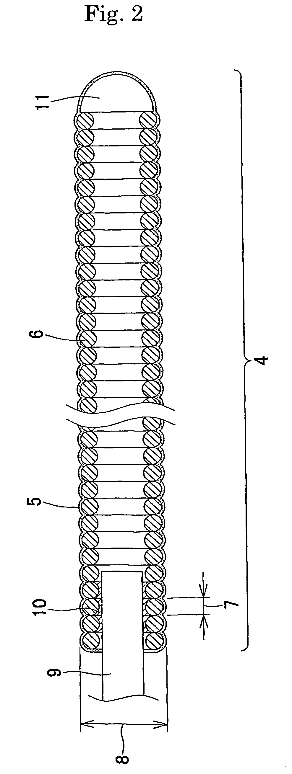
[0073] A platinum-tungsten (8%) alloy wire with a wire diameter of 45 μm was wound to form a coil with an outer diameter of 300 μm and a length of 4 mm. Using dimethylacetamide (manufactured by Nacalai Tesque, Inc.) as a solvent in which 5% lithium chloride (manufactured by Nacalai Tesque, Inc.) was dissolved; a 0.5% chitin (manufactured by Wako Pure Chemical Industries, Ltd.) solution was prepared. After the coil was dipped in the 0.5% chitin solution for one minute, the coil was dipped in 2-propanol (manufactured by Nacalai Tesque, Inc.) serving as a coagulant solution for 5 minutes to coagulate the chitin solution, and thereby the surface of the coil was coated with chitin. The solvent was removed by thorough washing with distilled water, followed by drying at 60° C. An embolization device coated with chitin was thereby obtained.

example 2

[0074] Using a 2% acetic acid (manufactured by Wako Pure Chemical Industries, Ltd.) aqueous solution as a solvent, a 2% Chitosan 1000 (manufactured by Wako Pure Chemical Industries, Ltd.) solution was prepared. An embolization device coated with chitosan was obtained as in Example 1 except that a 0.2 N sodium hydroxide (manufactured by Nacalai Tesque, Inc.) aqueous solution was used as a coagulant solution.

example 3

[0075] Using a 0.2 N sodium hydroxide (manufactured by Nacalai Tesque, Inc.) aqueous solution as a solvent, a 5% curdlan (manufactured by Wako Pure Chemical Industries, Ltd.) solution was prepared. An embolization device coated with curdlan was obtained as in Example 1 except that an aqueous solution containing 4% acetic acid (manufactured by Wako Pure Chemical Industries, Ltd.) and 26% sodium chloride was used as a coagulant solution.


PUM

PropertyMeasurementUnit
diameteraaaaaaaaaa
outer diameteraaaaaaaaaa

Abstract

An embolization device which is placed at a definite position in a vessel cavity in vivo to embolize the vessel cavity. More specifically speaking, an embolization device to be used for plugging a blood vessel or a aneurysm formed in a blood vessel. After being placed in a vessel cavity in vivo, this embolization device promotes not only thrombosis but also organization over the surrounding area, thereby exerting an excellent embolization effect on the vessel cavity. Namely, an embolization device for plugging a vessel cavity in vivo characterized by having biological response modifiers (BRM) which can promote organization and exert an enhanced embolization effect after being placed in a vessel cavity in vivo.

Description

TECHNICAL FIELD [0001] The present invention relates to an embolization device which is placed at a predetermined position in a vessel cavity in vivo to embolize the vessel cavity. More particularly, the invention relates to an embolization device which embolizes a blood vessel or a aneurysm formed in a blood vessel. BACKGROUND ART [0002] It is known that cerebrovascular diseases are broadly classified into hemorrhagic lesions, such as subarachnoid hemorrhage and intracerebral hemorrhage, and obstructive lesions caused by atheromatous clots or the like, and that cerebrovascular diseases rapidly develop and have serious prognoses. Above all, subarachnoid hemorrhage is a serious disease with a mortality rate of about 30% within 48 hours of onset. Furthermore, the frequency of rebleeding within two weeks after subarachnoid hemorrhage is 20% to 30%, and in the case of rebleeding, the mortality rate is extremely high at 70% to 90%. [0003] Rupture of cerebral aneurysms, such as a cerebral...

Claims


Application Information

Patent Timeline
Patent Type & Authority Applications(United States)
IPC IPC(8): A61B17/12A61L31/00A61L31/10A61L31/14
CPCA61B17/12022A61B17/12113A61B17/12145A61B2017/1205A61L31/10A61L2430/36A61L31/14C08L5/00A61B17/12A61L31/00
Inventor IWATA, HIROONISHIDE, TAKUJI
Owner KANEKA CORP
Why Eureka
Try Eureka