Optical pickup unit and information recording and reproduction apparatus

a technology of information recording and reproduction apparatus and optical pickup unit, which is applied in the direction of optical recording head, data recording, instruments, etc., can solve the problems of spherical aberration, large capacity of dvd, and inability to meet the demands of users in terms of capacity

Inactive Publication Date: 2005-12-08
RICOH KK
View PDF18 Cites 9 Cited by
  • Summary
  • Abstract
  • Description
  • Claims
  • Application Information

AI Technical Summary

Benefits of technology

[0020] Accordingly, it is a general object of the present invention to provide an optical pickup unit and an information recording and reproduction apparatus in which the above-described disadvantages are eliminated.

Problems solved by technology

The DVDs are larger in capacity than the CDs, but have yet to satisfy the demands of users in terms of capacity.
However, distances from an objective lens to the recording layers are different so that spherical aberration occurs in recording layers out of an optimum position.
This reduces yield rate, thereby affecting the cost to a considerable extent.
Further, the aging and temperature characteristics of the light-receiving element are subject to change.
Such a configuration, where each split beam is focused into a small spot and a plurality of light-receiving elements detect a given one of the split beams, is complicated and may impair the stability of the optical pickup unit.
This may reduce yield rate, thereby incurring an increase in cost.
However, in some semiconductor lasers, noise characteristics worsen as an output lowers.
As a result, the state of oscillation of the semiconductor laser becomes unstable so that the output of the semiconductor laser includes noise.
Further, noise is also generated in the output of the semiconductor laser by the operation of the semiconductor laser or a variation in environmental temperature.
However, when the light-emission power of the semiconductor laser is around the threshold current level, the light-emission power is affected by disturbances including those caused by the above-described returning light, so that variations are caused in the light-emission power.
In this case, therefore, the semiconductor laser is especially subject to the returning light to be unstable in emitting the laser beam.
Accordingly, the signal is deteriorated by noise caused in the output of the semiconductor laser.
If the amplitude level of the signal output through the current-voltage conversion amplifier is too low, a problem is caused in information reproduction.
However, as the NA increases, the rate of increase of aberration also increases.

Method used


Image

  • Optical pickup unit and information recording and reproduction apparatus
  • Optical pickup unit and information recording and reproduction apparatus
  • Optical pickup unit and information recording and reproduction apparatus

Examples


first embodiment

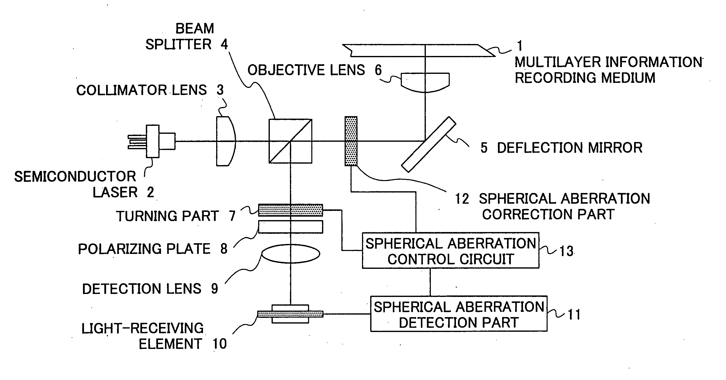
[0072]FIG. 5 is a schematic diagram showing an optical system of an optical pickup unit according to the present invention. The optical system of the optical pickup unit of FIG. 5 includes a multilayer information recording medium 1, a semiconductor laser 2 emitting a p-polarized laser beam, a collimator lens 3 collimates the laser beam emitted from the semiconductor laser 2 into parallel rays, a beam splitter 4 letting through the laser beam from the collimator lens 3 and deflecting a reflected light from the multilayer information recording medium 1, a deflection mirror 5 deflecting the laser beam, an objective lens 6 gathering the laser beam incident thereon with its optical characteristics such as numerical aperture and spherical aberration being optimized for one of the layers of the multilayer information recording medium 1, a turning part 7 that selectively turns the plane of polarization of the reflected light from the multilayer information recording medium 1 deflected by t...

second embodiment

[0100]FIG. 11 is a schematic diagram showing a configuration of an optical system of an optical pickup unit according to the present invention. The optical pickup unit of FIG. 11 includes a polarization beam splitter 30 and a turning part 31. In FIG. 11, the same elements as those of FIGS. 5 and 10 are referred to by the same numerals, and a description thereof will be omitted.

[0101] The optical pickup unit of the second embodiment is different from that of the first embodiment in the following points: [0102] (a) The polarization beam splitter 30 replaces the beam splitter 4 of the first embodiment. [0103] (b) The turning part 31, which replaces the turning part 7 of the first embodiment, is provided in the optical path between the polarization beam splitter 30 and the objective lens 20. [0104] (c) The turning part 31 includes a functional element corresponding to a ¼ wave plate, while the turning part 7 of the first embodiment is employed as a functional element corresponding to a ...

third embodiment

[0114]FIG. 12 is a schematic diagram showing a configuration of an optical system of an optical pickup unit according to the present invention. In FIG. 12, the same elements as those of FIG. 5 are referred to by the same numerals, and a description thereof will be omitted.

[0115] The optical pickup unit of the third embodiment is different from that of the first embodiment in that the turning part 7 is provided in the optical path from the semiconductor laser 2 to the multilayer information recording medium 1. The turning part 7 of the third embodiment is substantially equal to that of the first embodiment. The turning part 7 of the third embodiment is identical to that of the first embodiment in being formed of the liquid crystal element composed of the central region A and the peripheral region B as shown in FIG. 6 so that voltage is applied to a selected one of the central region A and the peripheral region B, thereby changing the direction of polarization of the light beam passin...


PUM

PropertyMeasurementUnit
poweraaaaaaaaaa
threshold voltageaaaaaaaaaa
voltageaaaaaaaaaa

Abstract

An optical pickup unit includes a light source emitting a light beam, an objective lens focusing the light beam onto an information recording medium, a light detection part receiving the light beam reflected from the information recording medium, and a light blocking part selectively blocking a part of the light beam with respect to a radial direction. The light blocking part is provided in an optical path of the light beam centered on an optical axis.

Description

BACKGROUND OF THE INVENTION [0001] 1. Field of the Invention [0002] The present invention generally relates to optical pickup units and information recording and reproduction apparatuses, and more particularly to an optical pickup unit recording information on and reproducing information from information recording media and an information recording and reproduction apparatus including such an optical pickup unit. [0003] 2. Description of the Related Art [0004] Disk-type optical information recording media widely used nowadays are compact disks (CDs) such as CD-ROMs, CD-Rs, and CD-RWs and digital versatile disks (DVDs) such as DVD-ROMs, DVD-Rs, and DVD-RWs. Some CDs have realized a recording density of 650 MB. The DVDs are larger in capacity than the CDs, but have yet to satisfy the demands of users in terms of capacity. In this context, a so-called multilayer disk, a disk formed of a plurality of recording layers instead of a single recording layer, has been developed for achieving ...

Claims


Application Information

Patent Timeline
Patent Type & Authority Applications(United States)
IPC IPC(8): G11B7/095G11B7/135G11B7/00
CPCG11B7/1369G11B7/13925G11B2007/0013
Inventor HIRAI, HIDEAKI
Owner RICOH KK
Why Eureka
Try Eureka