Organic EL display and method of manufacturing the same

a technology of organic el and display, which is applied in the manufacture of electrode systems, electric discharge tubes/lamps, and discharge tubes luminescent screens, etc., can solve the problems of difficult to maintain good color reproduction, difficult to achieve efficient and cheap manufacture of el, and difficult to raise the aperture ratio, etc., to achieve stable light emission characteristics, cure in a short time, and infiltration of moisture

Inactive Publication Date: 2005-12-15
FUJI ELECTRIC HLDG CO LTD
View PDF9 Cites 54 Cited by
  • Summary
  • Abstract
  • Description
  • Claims
  • Application Information

AI Technical Summary

Benefits of technology

[0014] It is therefore an object of the present invention to provide an outer periphery sealing constitution according to which precise alignment between the organic EL light-emitting layer and the color filters can be carried out, and curing can be carried out in a short time, and an organic EL display according to which light from the organic EL light-emitting layer can be transmitted to the color filters effectively without being reflected, infiltration of moisture and so on from the outside environment can be prevented, and stable light emission characteristics can be maintained over a long period, and a method of manufacturing such an organic EL display.

Problems solved by technology

In this case, with a constitution in which the light is extracted from the side of the substrate on which the TFTs are formed, due to the effect of wiring parts blocking the light, the aperture ratio cannot be raised.
In the case of a top emission type device in which light emitters of the three primary colors red, green and blue are arranged separated from one another in a matrix, light-emitting materials for red, green and blue must be arranged with high detail in the matrix, and hence it is difficult to carry out their manufacture efficiently and cheaply.
Moreover, drawbacks remain such as it being difficult to maintain good color reproduction over a long period due to the brightness change characteristics and driving conditions being different for the three types of light-emitting material.
In addition, when color filters are used with a backlight that emits white light, thus transmitting the three primary colors separated from one another, the problem of making the backlight have high efficiency remains.
Moreover, there is a problem of light emitted from organic EL light-emitting layer 4 being reflected at an air layer interface where the refractive index changes greatly due to the influence of internal space 32 formed between the two substrates.
However, if the elastic modulus of the filled material is high, then peeling away from the organic EL light-emitting layer or the color filter layers will occur due to thermal stress produced upon a change in the temperature of the usage environment.

Method used


Image

  • Organic EL display and method of manufacturing the same
  • Organic EL display and method of manufacturing the same

Examples


example 1

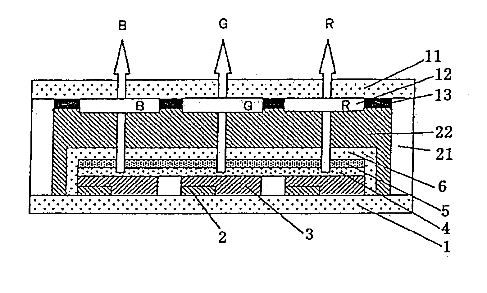
[0064] TFTs 2, anodes 3, organic EL light-emitting layer 4, cathode 5, and protective layer 6 were formed in this order on substrate 1 (a glass substrate in the present example) as shown in FIG. 1. Next, color filters 12 and black mask 13 were formed in this order on transparent substrate 11 (a transparent glass substrate in the present example). The two substrates formed in this way were then subjected to the following process under a dry nitrogen atmosphere (oxygen and moisture concentration both not more than 1 ppm) in a glove box.

[0065] Outer periphery sealing layer 21 using a UV-curable adhesive (made by Three Bond, trade name: 30Y-437), which is an epoxy type material, was formed using a dispenser robot (an adhesive applying apparatus, driven by a XY robot) on an outer peripheral portion of glass substrate 1 on the organic EL light-emitting layer side, and transparent glass substrate 11 was bonded on from the color filter 12 side.

[0066] At this time, outer periphery sealing ...

example 2

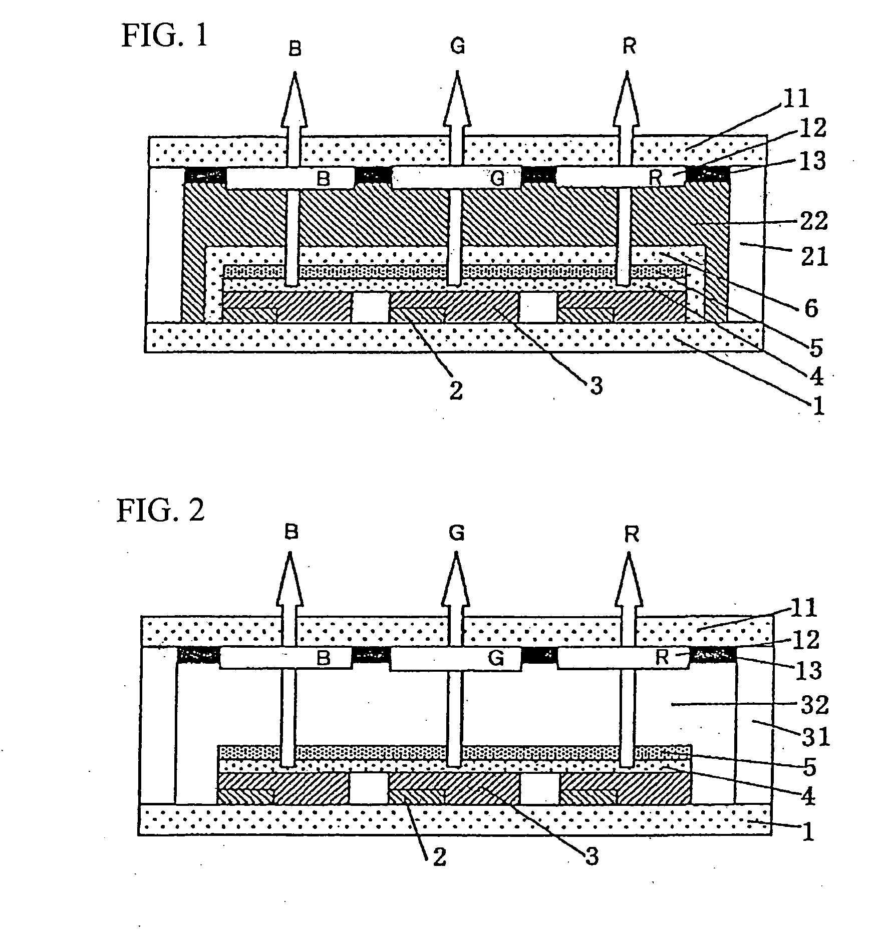
[0072] The constitution of the substrates in the present embodiment was the same as in Example 1. However, a visible light-curable adhesive was used for outer periphery sealing layer 21, and a transparent silicone gel material was used for internal sealing layer 22. The visible light-curable adhesive was, for example, Luxtrak LCR0275 (trade name) made by Toagosei Co., Ltd., this being an acrylic material. Moreover, the curing conditions were a wavelength of 400 nm, an intensity of 100 mW / cm2, and an irradiation time of 30 seconds. Such a visible light-curable adhesive is advantageous in terms of the equipment cost, since the irradiation apparatus is cheaper than for a UV-curable adhesive. The transparent silicone gel material was KE104Gel (trade name) made by Shin-Etsu Chemical Co., Ltd., and had a refractive index of approximately 1.45, and a compression modulus of not more than 0.5 kg / mm2.

[0073] According to the present invention, as a result of adopting the constitution describe...


PUM


Abstract

An organic EL display is displayed. The display is manufactured sealing and joining an organic light emitter constituted from thin film transistors, anodes, a light-emitting layer, a cathode and a protective layer which are laminated on a substrate, together with a laminated body of color filters and a black mask formed on a transparent substrate. The organic EL light-emitting layer is aligned with the color filters during the process of sealing the substrate and the transparent substrate using an outer periphery sealing layer and an internal sealing layer. The outer periphery sealing layer provides precise alignment between the organic EL light-emitting layer and the color filters and rapid fixing between them can be carried out, and prevents infiltration of moisture from the outside environment. The internal sealing layer prevents reflection of light from the organic EL light-emitting layer, and hence the light can be transmitted to the color filters effectively. The device and method prevent peeling apart due to cure shrinkage, peeling apart due to thermal stress from the temperature of the environment, and infiltration of moisture from the outside environment, so that stable light emission characteristics can be maintained over a long period.

Description

CROSS REFERENCE TO RELATED APPLICATIONS [0001] This is a continuation of International Application PCT / JP2003 / 07564, having an international filing date of Jun. 13, 2003; this International Application was not published in English, but in Japanese, as WO2004112436.BACKGROUND OF THE INVENTION [0002] A. Field of the Invention [0003] The present invention relates to an organic EL (electroluminescent) display that is excellent in terms of high detail, environmental resistance and productivity, and can be used in a wide range of applications such as a display of mobile terminal equipment, industrial measuring equipment or the like. More particularly it relates to a so-called top emission type organic EL display and a method of manufacturing the same. [0004] B. Description of the Related Art [0005] In recent years, there have been rapid advances in increasing the speed of, and expanding the range of application of, information communication. Amid this, there have been many inventions with...

Claims


Application Information

Patent Timeline
Patent Type & Authority Applications(United States)
IPC IPC(8): H05B33/04H05B33/12H05B33/14H01L51/52H05B33/10H01L27/32H05B33/08
CPCH01L27/322H01L27/3244H01L2251/5315H01L51/5246H01L51/5253H10K59/38H10K59/12H10K50/8426H10K2102/3026H10K50/844
Inventor YANAGAWA, KATSUHIKO
Owner FUJI ELECTRIC HLDG CO LTD
Why Eureka
Try Eureka