Image compression for rapid high-quality imaging

a digital image and compression technology, applied in the field of lossless or reversible, near lossless, lossy compression and decompression of digital image data, can solve the problems of increasing system bandwidth, increasing complexity and cost of system, and requiring a lot of silicon to be implemented in hardware and software, so as to reduce cost, increase performance, and be easily implemented

Active Publication Date: 2005-12-15
PHASE ONE
View PDF8 Cites 68 Cited by
  • Summary
  • Abstract
  • Description
  • Claims
  • Application Information

AI Technical Summary

Benefits of technology

[0067] A line based compression scenario which reduces the need for external or internal buffer for temporary storage and thereby reduce cost and increase performance.
[0068] The algorithm can easily be implemented in a way that makes it very suitable for image sensors with multiple outputs—the small silicon footprint enables easy use of parallel image compression. Multiple imager outputs can also be supported by customizing the algorithm for a certain amount of input-channels, but that requires additional R&D and Test resources, and performance is harder to increase due to reduced parallel nature.

Problems solved by technology

All in all this results in increasing demands to system bandwidths, transporting media bandwidth as well as storage capacity of both temporary storage (e.g. RAM) and permanent storage (e.g. HDD).
Prior solutions based on industry standards like JPEG, require a lot of silicon to be implemented in hardware and are often too slow when implemented in software—this is particular the case if the bit-depth of pixels increase from the traditional 8 bits per color to e.g. 16 bits per color.
This increases the complexity and cost of the system and reduces the ability to generate high-quality images, as a lot of image enhancement is required for optimum results, sometimes in combination with user interaction.
The method compresses image data in a lossy manner by dividing down pixel values by a loss factor and thereby creating an evenly distributed linear loss in the pool of image data.
From an image-quality point of view, it is a disadvantage that this approach will increase the amount of digital noise in the darker areas of the resulting decompressed image as presented on either paper or a computer monitor.
This instantly reduces the possibility of generating a high quality image at a later stage.
This form of encoding works well with image data with low color bit-depth (e.g. 8 bits), but often yields poor results when used with image data with high color bit-depth (e.g. 16 bits) and a relatively high amount of entropy, which are all characteristics for high-quality imaging.
Another limitation of the implementation described in U.S. Pat. No. 6,614,483 is that it requires an external or internal buffer to hold at least two adjacent lines of image data to be able to do simple color interpolation.
With high resolution image sensors, the required amount of temporary storage can be quite high and thereby increase system cost if the buffer is implemented together with the block that carries out the compression itself.
Using cheaper external storage (e.g. DRAM) will often be unacceptable from a performance point of view.

Method used


Image

  • Image compression for rapid high-quality imaging
  • Image compression for rapid high-quality imaging
  • Image compression for rapid high-quality imaging

Examples


Embodiment Construction

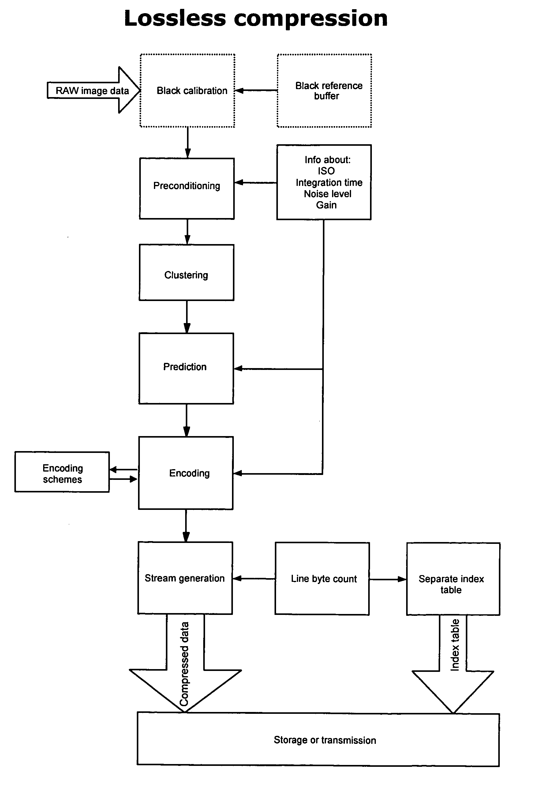
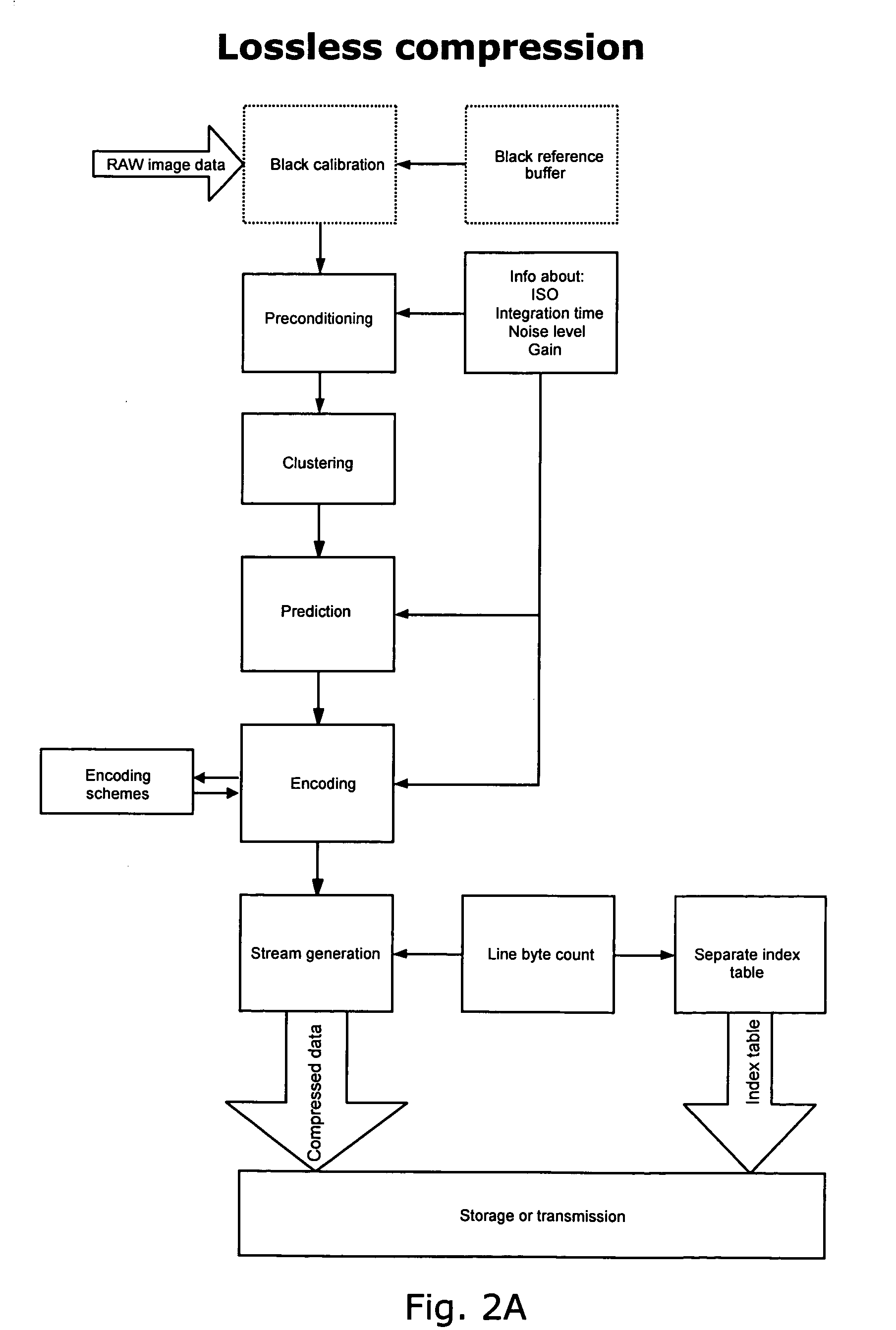
[0081] The invention provides a digital imaging system having a compression section implementing an algorithm for lossless or near-lossless compressing high-quality image data. Corresponding block diagrams of the algorithm are shown in FIGS. 2A and B. The algorithm contains a novel structure which enables very fast on-the-fly compression of image data. The digital imaging system can be a digital camera back for a portable digital camera controlled by a camera operation system.

[0082] In the following, an embodiment of the part of the image system related to the compression of images is described in relation to FIG. 3. The compression section 10 is positioned close to an image sensor 12, receiving data directly from the sensor 12 through analog amplifier 13 and analog-to-digital converter (ADC) 14. The compression section comprises a number of blocks and processors for performing various operations in relation to the compression, and is connected to a memory 11 holding routines, tabl...


PUM


Abstract

The invention relates to lossless, near-lossless, and lossy compression and decompression of digital image data. Image data can be compressed and decompressed on-the-fly with no need for external RAM resources for temporary data storage while compressing/decompressing image data. Implementing the algorithm only requires a very limited amount of silicon and yields very high performance in relation to very low power consumption. The described implementation is optimized for raw image data from a sensor with a Bayer filter pattern but can be used on data from image sensors with any color filter. The compression algorithm contains a line indexing format which enables very fast subsampling of an already compressed image and the possibility to decompress only parts of an image—this improves performance and reduces the need for temporary RAM storage greatly when zooming and in postprocessing.

Description

FIELD OF INVENTION [0001] The present invention relates to lossless or reversible, near-lossless, and lossy compression and decompression of digital image data. In particular, the invention relates to (de)compressing image data on-the-fly with no need for external RAM resources for temporary data storage. BACKGROUND OF THE INVENTION [0002] Image resolution is ever increasing and so are the accompanying frame rates. All in all this results in increasing demands to system bandwidths, transporting media bandwidth as well as storage capacity of both temporary storage (e.g. RAM) and permanent storage (e.g. HDD). The strains on all these function blocks will be reduced if image data is compressed. Historically memory and permanent storage media bandwidths have not been increasing as rapidly as data processing means, which indicates that using on-the-fly image compression will yield much higher system performance than just adopting technological improvements in memory and permanent storage...

Claims


Application Information

Patent Timeline
Patent Type & Authority Applications(United States)
IPC IPC(8): G06K9/36H04N7/26H04N19/593
CPCH04N19/105H04N19/593H04N19/184H04N19/14H04N19/182H04N19/132
Inventor MOLGAARD, CLAUSROGON, THOMAS ALEXANDERANDERSEN, THOMAS
Owner PHASE ONE
Why Eureka
Try Eureka