Analog external cavity laser

a laser and external cavity technology, applied in the field of external cavity laser light sources, can solve the problems of reducing the transmission efficiency ratio of laser sources with narrower linewidth than typical dfbs, affecting the spread of catv and wireless distribution to 1550 nm networks, and affecting the transmission efficiency ratio of laser sources

Inactive Publication Date: 2005-12-22
K2 OPTRONICS +1
View PDF52 Cites 51 Cited by
  • Summary
  • Abstract
  • Description
  • Claims
  • Application Information

AI Technical Summary

Benefits of technology

[0013] The present invention relates to the design, packaging, and manufacturing of direct-modulated analog external cavity lasers (ECLs) having improved cost-performance ratio for transmission of analog and semi-analog (such as quadrature amplitude modulated (QAM)) signals, particularly for broadcast, digital simulcastand narrowcast (QAM) applications.
[0014] Furthermore, some embodiments of the present invention relate to the design of direct-modulated analog ECLs with simultaneously (i) controlling chirp (from extremely low to high in magnitude); (ii) low intermodulation distortions (second- and third orders); and low Relative Intensity Noise (RIN) which provide high performance and low cost devices, methods and / or systems for transmission of analog signals in the 1550 wavelength range.
[0015] The present invention further relates to and includes packaging design and packaging criteria (particularly 14-pin butterfly packaging common in the industry) and with the external laser cavity implemented using a fiber Bragg grating element terminated with an integrating high coupling lens and light source (Fabry-Perot (FP) chip), all mounted on the same solid substrate. Such an approach provides long-term package stability that is particularly advantageous in analog transmission systems.

Problems solved by technology

However, widespread deployment of 1550 nm networks for CATV and wireless distribution has been hampered by several factors, including the chirp produced by direct-modulated DFB lasers.
In addition, the deployment of new and more efficient modulation schemes has been delayed due to as yet unmet requirements for higher performing, lower cost optical transmitters.
However, utilizing QPSK techniques typically requires low cost laser sources having narrower linewidth than typical DFBs that are currently commercially available (see, for example, S. Norimatsu, et al.
Among the major barriers to the wider use of direct-modulated DFBs around the 1550 nm band is the high chirp and the relatively high intrinsic distortion of the solitary DFB laser.
Another limitation of direct-modulated DFBs operating near the 1550 nm band is the relatively large linewidth, of the order of 1 MHz.
Such effects lead to limited transmission performance under high channel loadings and for longer transmission distances.
Multiple approaches have been proposed to address these issues, but they generally have technical and / or cost drawbacks.
These solutions include (a) The use of dispersion compensators, which are usually expensive, complex, and cumbersome, typically requiring customization of each fiber span.
This combination can exhibit practically zero chirp in some circumstances, but the high cost makes this solution over-engineered and too expensive for all but a few specialized, typically low volume, applications.
(c) The use of electro-absorption modulated lasers (EMLs) which suffer from narrow operating margins, the requirement for complex predistortion circuitry to reduce the relatively large intrinsic harmonic distortion, and the low carrier-to-noise ratio (CNR) (due to the relatively low optical output power).
The main drawbacks of such techniques include the added expense and the need for customization in manufacturing to accommodate different levels of distortion correction.
However, this method has had very limited commercial success because of its high cost and complexity (for example, see H. Sung et al., “Dependence of Semiconductor Laser Intermodulation Distortions on Fiber Length and its Reduction by Optical Injection Locking,” Conference Proceedings, Paper WE2 10, p.

Method used


Image

  • Analog external cavity laser
  • Analog external cavity laser
  • Analog external cavity laser

Examples


Embodiment Construction

[0046] After considering the following description, those skilled in the art will clearly realize that the teachings of the invention can be readily utilized for the design, fabrication, packaging and / or use of external cavity lasers (ECLs), particularly analog ECLs

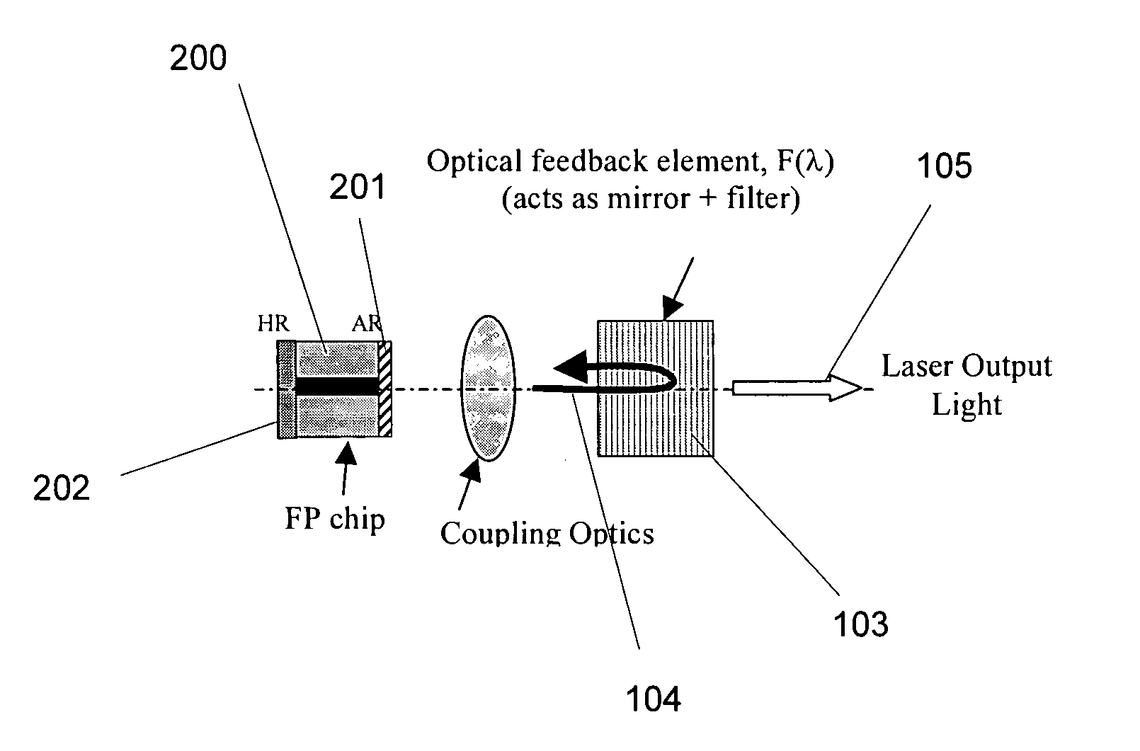
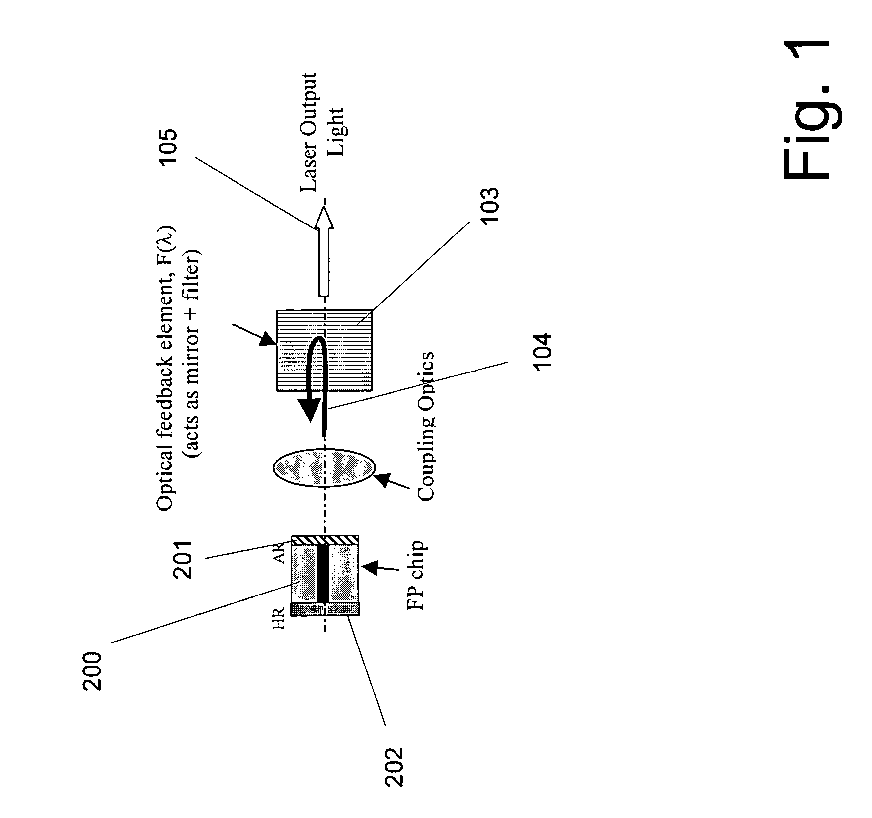
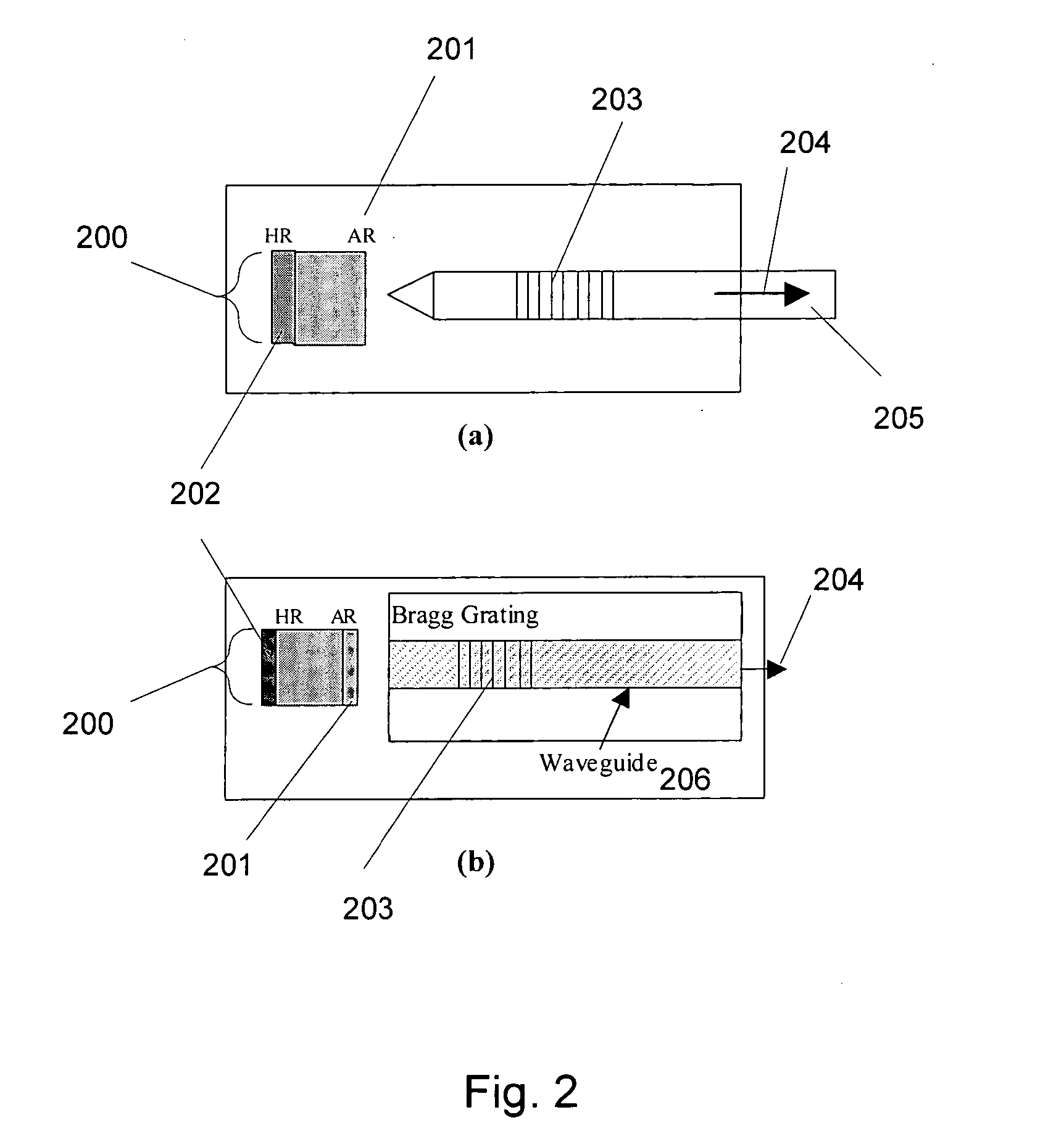
[0047] The technologies described herein relate to analog external cavity lasers including techniques for designing, packaging and improving the performance of ECLs for use in analog and CATV fiber optic communications systems. This field of application is by way of example and not limitation since systems, techniques, processes, devices and materials described herein can find applications in other fields as well. The analog ECLs described herein are direct-modulated laser sources providing significant advantages compared with other devices and systems for analog optical transmission. These advantages include higher performance in terms of distortion and chirp (for example), at lower costs and with improved design margin...


PUM


Abstract

The present invention relates to the analog external cavity lasers (ECLs) including designs, materials, methods of manufacturing and methods of use for such ECLs and packages for such ECLS. Numerous criteria are presented that lead to improved cost / performance for ECLs and for systems incorporating such ECLs.

Description

CROSS REFERENCE TO RELATED APPLICATIONS [0001] This application claims priority from provisional patent application Ser. No. 60 / 558,927 filed Apr. 2, 2004, and provisional patent application Ser. No. 60 / 562,762, filed Apr. 16, 2004, and provisional patent application Ser. No. 60 / 638,679 filed Dec. 23, 2004, pursuant to one or more of 35 U.S.C. § 119, § 120, § 365. The entire contents of all cited provisional patent applications are incorporated herein by reference for all purposes.BACKGROUND OF THE INVENTION [0002] 1. Field of Invention [0003] This invention relates generally to the field of laser light sources and, more particularly, to external cavity laser light sources. [0004] 2. Description of the Prior Art [0005] Directly modulated distributed feedback (DFB) laser diodes are widely used in many applications, including the transmission of multiple channels of analog modulated signals as typically used for analog broadcast, digital simulcast and narrowcast (QAM-format) in cable ...

Claims


Application Information

Patent Timeline
Patent Type & Authority Applications(United States)
IPC IPC(8): H01S3/04H01S5/00H01S5/02H01S5/022H01S5/024H01S5/028H01S5/042H01S5/0683H01S5/0687H01S5/14H01S5/40H04B10/04
CPCH01S3/1055H01S3/1398H01S5/0064H01S5/0078H01S5/02216H01S5/02415H01S5/02438H01S5/028H01S5/0427H01S5/06804H01S5/0683H01S5/0687H01S5/141H01S5/147H01S5/4012H01S5/4062H01S5/4087H01S2301/03H01S5/02325H01S5/02251
Inventor KUPERSHMIDT, VLADIMIRKUSNADI, FRANSMAJOR, JOHNSIALA, SABEUR
Owner K2 OPTRONICS
Why Eureka
Try Eureka