Fuel cell, its fuel-feeding system, fuel cartridge and electronic equipment

a fuel cell and fuel-feeding technology, applied in the field of fuel cells, can solve the problems of increasing power consumption due to many functions, and achieve the effects of convenient use, convenient operation and convenient storag

Inactive Publication Date: 2005-12-22
HITACHI LTD
View PDF4 Cites 21 Cited by
  • Summary
  • Abstract
  • Description
  • Claims
  • Application Information

AI Technical Summary

Benefits of technology

[0018] Examples of the aqueous solution fuel held in the fuel cartridge include an aqueous methanol solution. One or more propellant gases are selected from, for example, pressure gas such as carbon dioxide, nitrogen, argon, air or the like or pressure-liquefied gas such as butane or flon. The present invention having the aforesaid configuration can be used as power supply systems for portable equipments that are more compact, more light-weight, have many functions and can be easily used at any time at any place.
[0019] According to the present invention, the fuel can be fed to the fuel cell from the fuel cartridge by a spray principle (using propellant gas). Since the fuel is an aqueous solution fuel instead of a gaseous fuel, it is possible to discharge a gas produced by a power generation operation (electrochemical reaction) as performing a gas-liquid separation between the produced gas and the aqueous solution fuel. Accordingly, a fuel is not substantially discharged in air, so that a system can be operated with high fuel efficiency. The case where the fuel is an aqueous methanol solution will be explained. An aqueous methanol solution is a liquid under ordinary temperature and atmospheric pressure. Therefore, there is no chance that a fuel, which should be fed to a fuel cell, is partly discharged to the outside without being used as a fuel, like dimethyl ether that is gas under atmospheric pressure. Consequently, chemical energy possessed by a fuel is efficiently converted into electric energy.
[0020] The use of the ejection effect of the propellant gas can realize a fuel cell system not requiring a mechanical auxiliary power such as a pump for feeding a fuel. It should be noted that, depending upon a configuration of a system, a liquid-feeding pump can be used together, and such a system can be included in the spirit of the invention.

Problems solved by technology

In recent years, the advent of New-type power supplies for portable equipments which have high energy density and substitutes for Li ion secondary battery have been expected as the demands of an increase in the energy density due to using a power supply at any time at any place, and an increase in power consumption due to many functions.

Method used


Image

  • Fuel cell, its fuel-feeding system, fuel cartridge and electronic equipment
  • Fuel cell, its fuel-feeding system, fuel cartridge and electronic equipment
  • Fuel cell, its fuel-feeding system, fuel cartridge and electronic equipment

Examples


Embodiment Construction

[0037] An embodiment of the present invention will be explained.

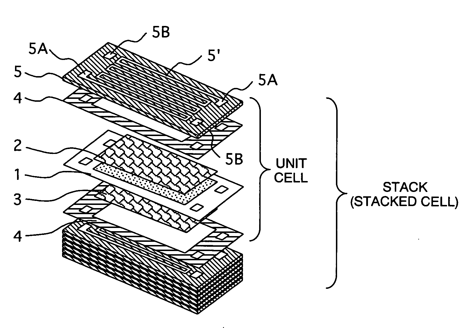
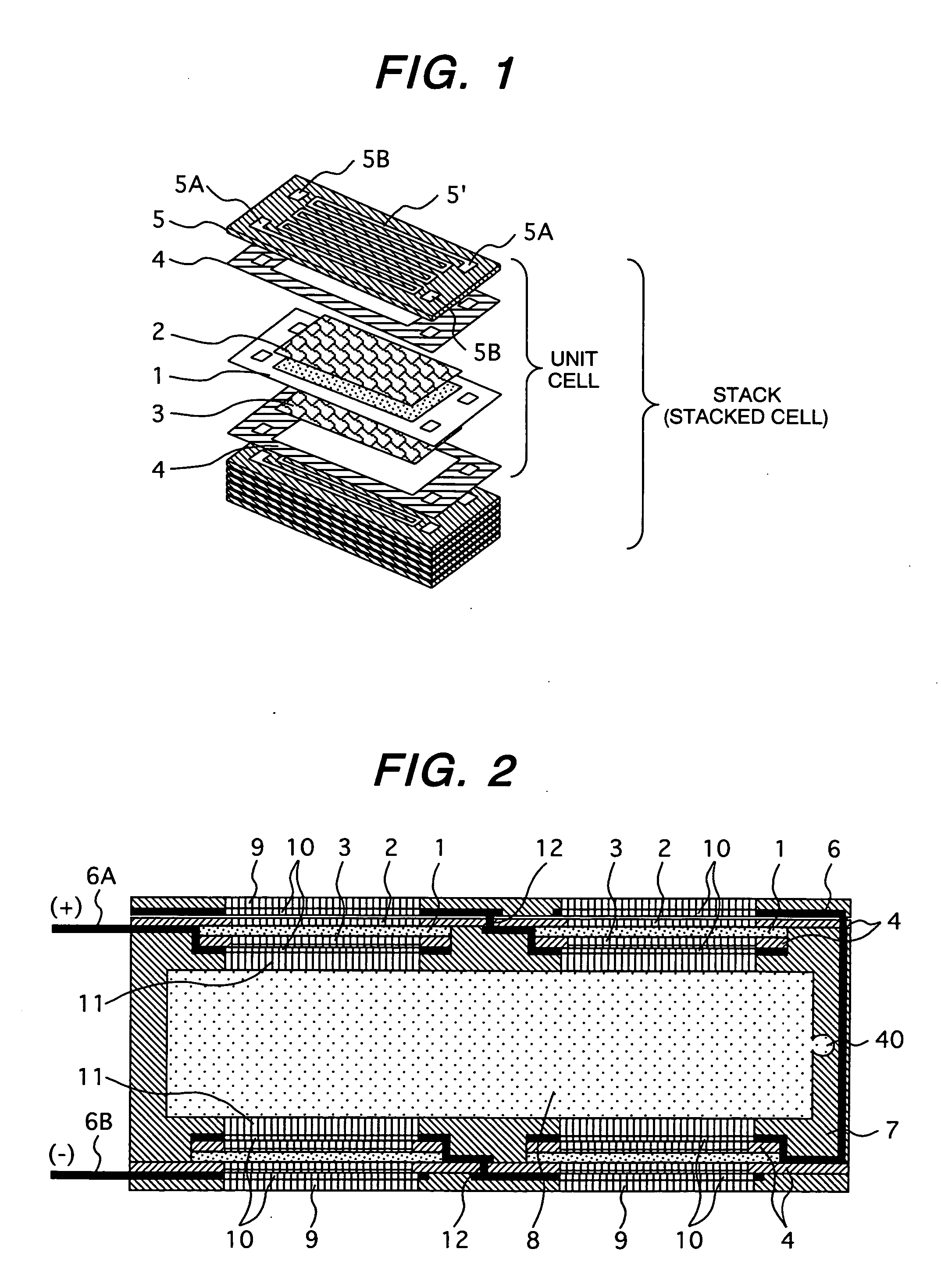
[0038]FIGS. 1 and 2 respectively show a fuel cell to which the present invention is to be applied. FIG. 1 is an exploded perspective view of a stack type fuel cell, while FIG. 2 is a partial sectional view of a panel type fuel cell.

Stack Type Fuel Cell

[0039] A fuel cell using a solid high polymer membrane is generally equipped with a plate membrane / electrode assembly (MEA: Membrane Electrode Assembly) wherein electrodes (anode and cathode) supporting a porous electrode catalyst are bonded on both surfaces of a solid electrolyte membrane; and a conductive separator. These are defined as a unit cell (single cell), whereby a plurality of unit cells are stacked to compose a fuel cell stack.

[0040] Specifically, as shown in FIG. 1, a unit cell is composed of an MEA 1 having an anode (fuel electrode) and cathode (air electrode) bonded on both surfaces of a solid high polymer electrolyte membrane, a cathode diffusion layer...


PUM

PropertyMeasurementUnit
open-circuit voltageaaaaaaaaaa
voltageaaaaaaaaaa

Abstract

An aqueous solution fuel is fed to a fuel cell by using a propellant gas composed of a pressure has or pressure-liquefied gas. The aqueous solution fuel and the propellant gas are held in an exchangeable fuel cartridge. An ejector for ejecting the aqueous solution fuel from the fuel cartridge to the fuel cell with the propellant gas is provided at the side of the fuel cartridge or at the side of the fuel cell.

Description

CLAIM OF PRIORITTY [0001] The present application claims priority from Japanese application serial no. 2004-177069, filed on Jun. 15, 2004, the contents of which are hereby incorporated by references into this application. BACKGROUND OF THE INVENTION [0002] The present invention relates to a fuel cell, its fuel-feeding system, fuel cartridge and electronic equipment (for example, a portable electronic equipment such as a cellular phone, personal digital assistant, notebook type personal computer, portable camera or the like) using the same. [0003] A fuel cell is composed at least a solid or liquid electrolyte and two electrodes (anode and cathode) that induce an electrochemical reaction, and is a power generator wherein chemical energy possessed by the fuel is directly converted into electric energy with high efficiency. [0004] Used for the fuel is hydrogen chemically converted from fossil fuels or water; methanol, alkali hydride or hydrazine that is a liquid or a solution in an ord...

Claims


Application Information

Patent Timeline
Patent Type & Authority Applications(United States)
IPC IPC(8): H01M8/00H01M8/04
CPCH01M8/00H01M8/04089H01M8/04208Y02E60/50Y02B90/18Y02E60/523H01M2250/30Y02B90/10
Inventor KAMO, TOMOICHIKUBOTA, OSAMUSOUMA, KENICHI
Owner HITACHI LTD
Why Eureka
Try Eureka