Fuel control module

a technology of fuel control module and control module, which is applied in the direction of liquid fuel engine, positive displacement liquid engine, piston pump, etc., can solve the problems of high cost and space occupation of multiple components, leakage internal, and high power consumption of gear pump, and achieve high pressure and flow rate, high accuracy and efficiency

Active Publication Date: 2005-12-29
JANSENS AIRCRAFT SYST CONTROLS
View PDF14 Cites 27 Cited by
  • Summary
  • Abstract
  • Description
  • Claims
  • Application Information

AI Technical Summary

Benefits of technology

[0013] The present invention provides an entire fuel control system in a single, compact, yet highly accurate and efficient modular unit. The fuel control module provides high pressure and flow rates of non-pulsed liquid fuel, while exhibiting very low leakage and having excellent dry lift and turn-down capabilities. These attributes and its compact form factor, metering accuracy and high temperature and pressure capabilities make it suitable for fuel delivery to gas turbines, particularly jet engines in aircraft where space and weight restrictions are stringent.
[0018] Yet another aspect of the invention provides a fuel control module with a housing defining interior fluid and dry chambers. The fluid chamber contains the pump and the pump motor, including stator and rotor, and receives fuel through an inlet. The dry chamber is isolated from fuel and contains an electronic motor drive. The drive controls the motor to operate a movable operating member of the pump to move fuel from the inlet through the fluid chamber to an outlet. The pump and motor are thus immersed in fuel such that the pumped fuel cools the motor and other internal components. Preferably, the motor is frameless to allow for better motor cooling.
[0019] The pump is preferably a highly accurate metering pump suitable for operation over a pressure range of about 0 to 800 psig in aggravated temperature conditions. Preferably, the pump has at least one operating member in the form of a double-ended spool piston. More preferably, there are two such spool pistons arranged in parallel and operated by a cam arrangement. The pistons can having one or more circumferential pressure balancing grooves to collect debris in the piston chambers and prevent binding of the pistons. This allows the pistons to slide smoothly within the piston chambers with minimal clearances, which in turn provides low internal leakage without the use of piston seals. Residual air space at top dead center is minimized to improve dry lift capability. Also, low pressure drop valves, such as reed valves, and open weave type filters can be used at the inlet to allow for very low inlet pressure, in the range of 2-5 psi above true vapor pressure, without cavitation or the need for a boosted inlet.

Problems solved by technology

The use of multiple components is expensive and occupies space, which is especially limited for propulsion systems.
However, such combined devices must meet both the extreme pump and the metering requirements for turbine engines.
Gear pumps consume a lot of power and leak internally and are therefore less than ideal for jet engine use.
Moreover, due to reliability concerns, gear pumps used for propulsion applications typically are powered by an engine driven gear box (rather than an electric motor) and therefore must be coupled to a separate metering valve via suitable fuel lines, which increases expense and occupies additional space.
While the aforesaid metering pump provides a marked improvement in accurate fuel metering at high flow rates, the diaphragms have pressure limitations that can make it less suitable for certain sustained high pressure applications.
These additional components may require their own housings as well as conduit and other fluid and electrical line connections, thus increasing the space and weight requirements of the system.
Further, the use of several separate components makes installation and replacement of the control system more time consuming and costly.
However, this comes with somewhat reduced filtering capacity.
Excessive debris in the pump can cause binding of the operating member, and reduce its efficiency or lead to pump failure.

Method used


Image

  • Fuel control module
  • Fuel control module
  • Fuel control module

Examples


Embodiment Construction

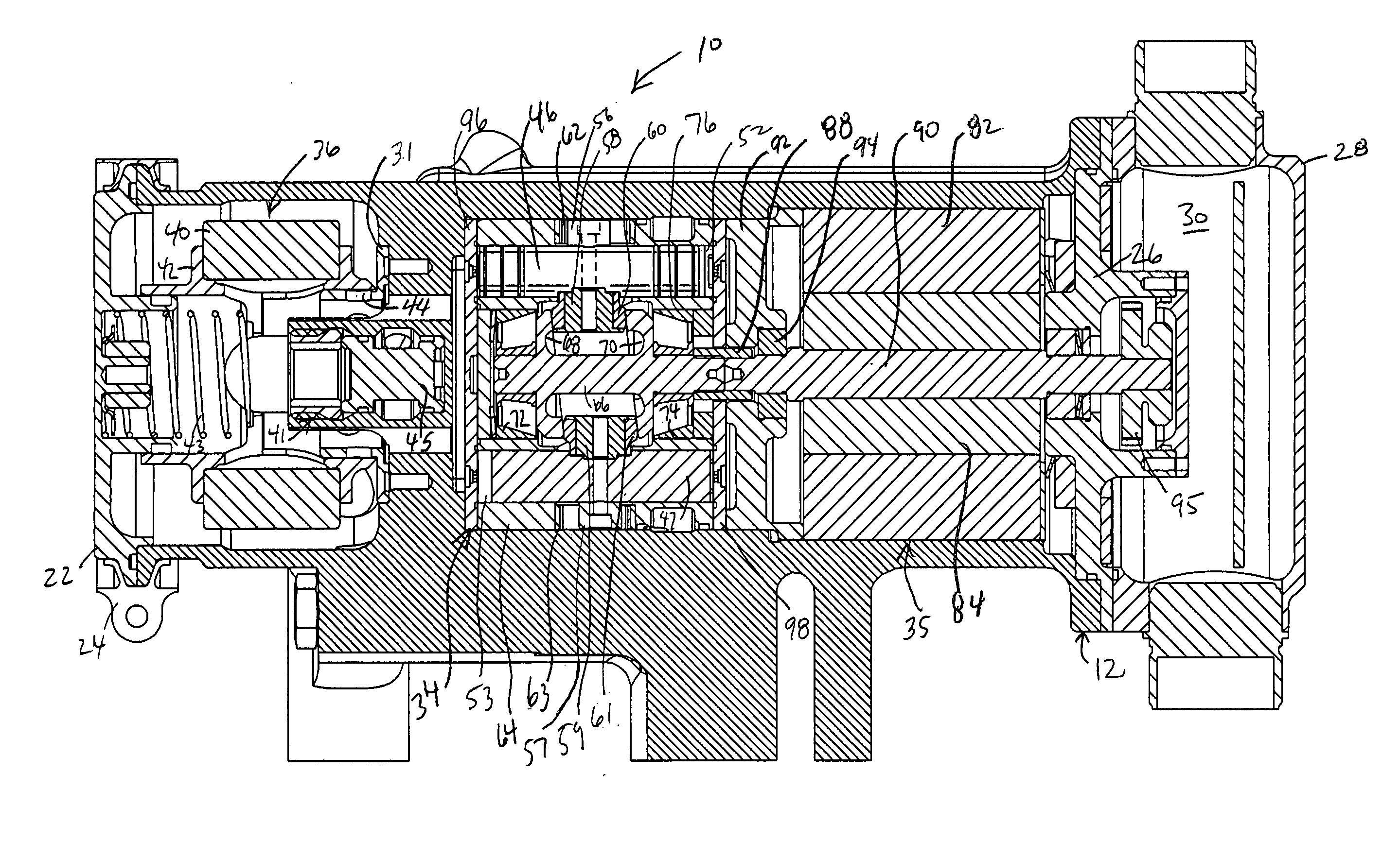
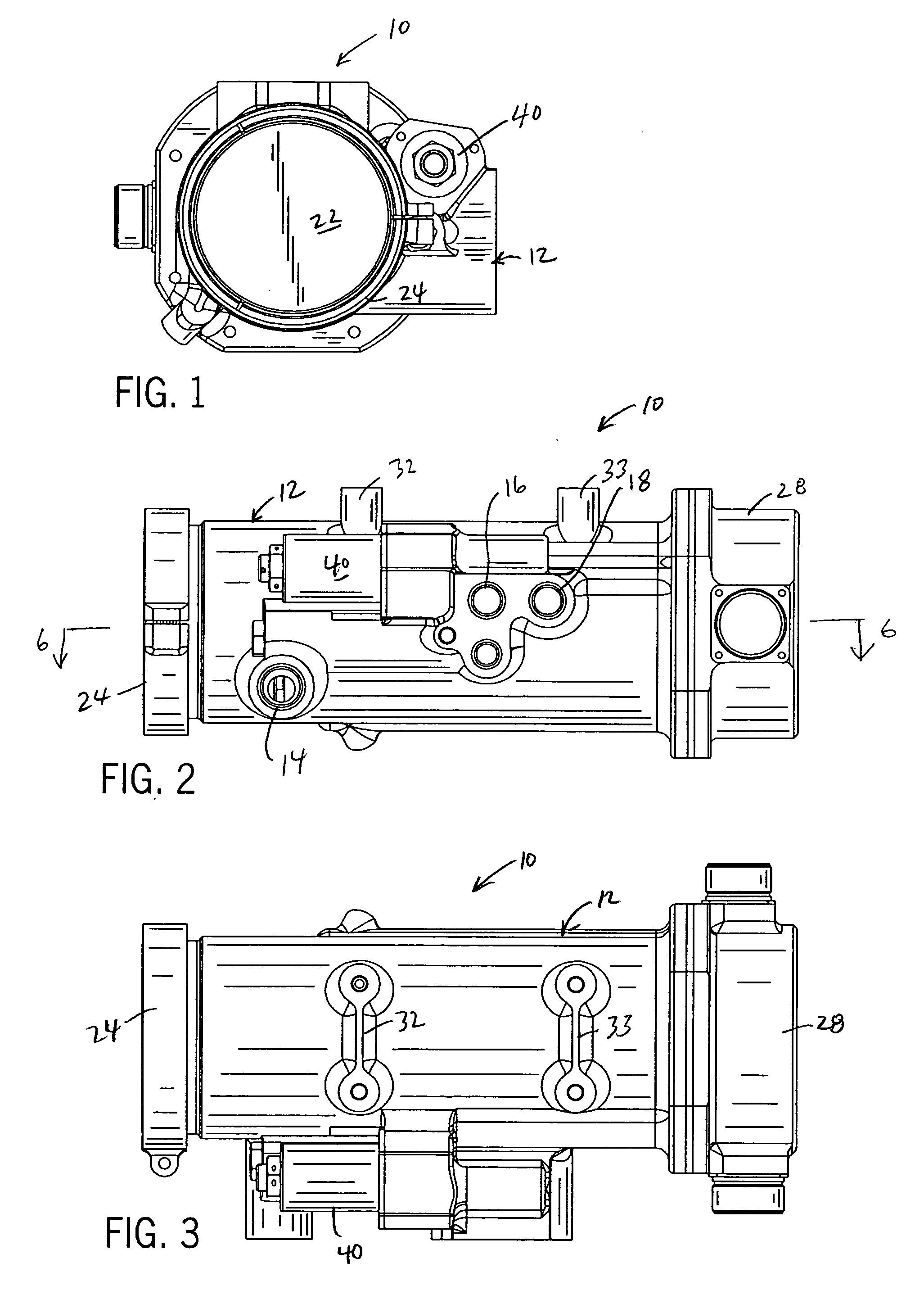
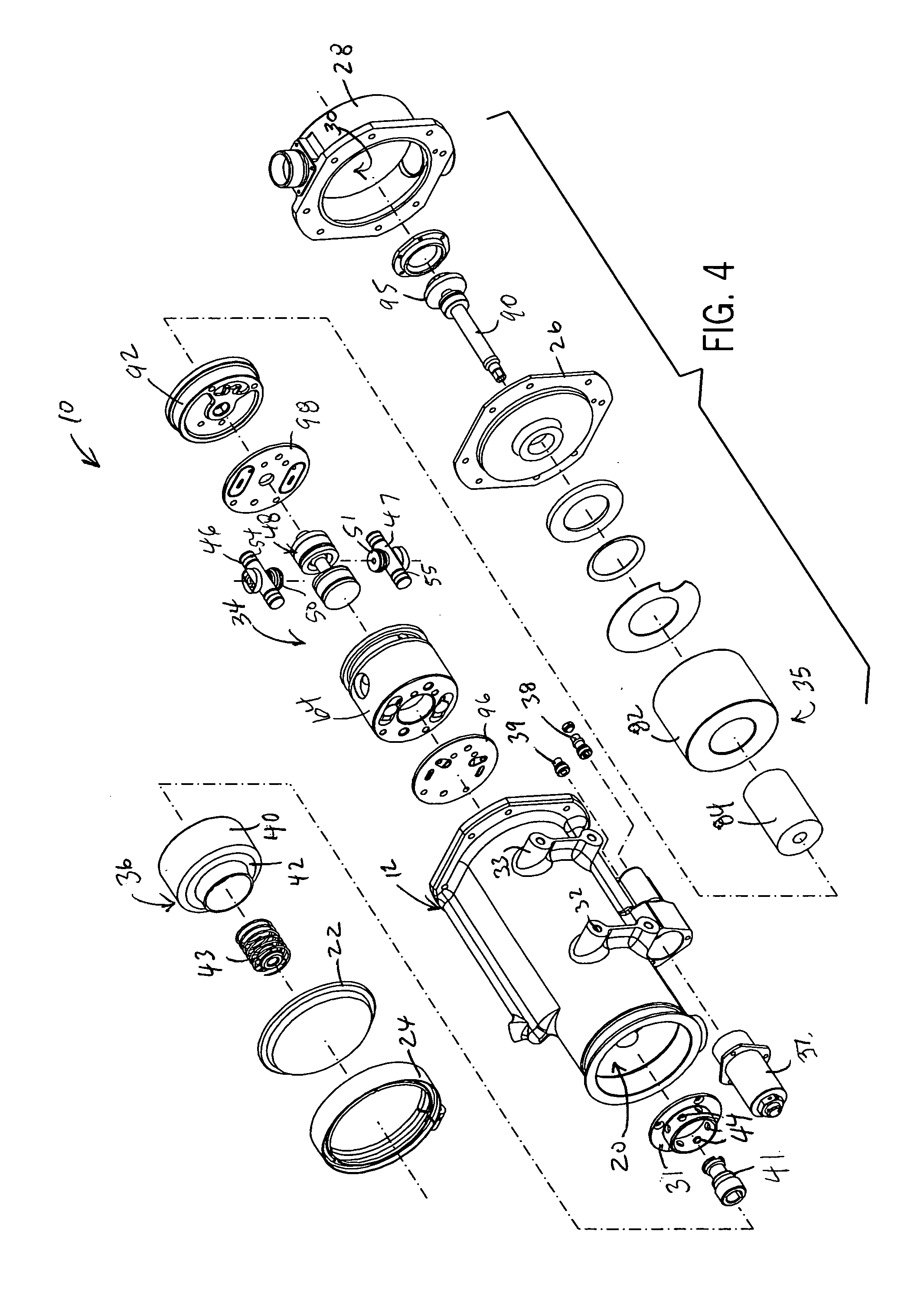
[0029] The present invention provides a fuel control module (“FCM”), generally referenced in the drawings by number 10, that fits in line between a fuel supply 11 and a fuel consuming device 13, for example which can be a gas turbine engine for power generation or propulsion applications, such as a jet engine or auxiliary power unit therefor consuming standard jet fuel (Jet A, Jet B, JP4 or JP5). In typical applications, the FCM 10 is electrically coupled via a 2-way bus to a remote master computer that controls high level fuel management and other system operations.

[0030] The FCM 10 is designed to provide a single device incorporating all of the components for controlling fuel delivery to the engine downstream from the master computer and fuel supply. Installation, as well as serviceability and replacement, of these components is thus simplified. The modular nature of the FCM 10 also allows it to be swapped easily for another unit having different operating parameters should fuel ...


PUM


Abstract

A fuel control system is provided in a single compact modular unit. The unit includes a motor driving a highly accurate cam-operated double-acting piston metering pump, both of which are contained in a liquid fuel environment. As the liquid fuel is pumped it works to cool internal components including the motor. An electronic motor drive is contained in a dry chamber of the unit for controlling operation of the motor and pump and is cooled indirectly by the fuel as well. A pressure sensitive flow divider is also included for selectively providing one or multiple output fuel flow paths depending upon whether a pressure threshold is reached, for example to send fuel to primary and secondary burner nozzles. Filter, filter bypass, pressure relief, and fuel shut-off components are also integrated into the single modular unit.

Description

CROSS-REFERENCE TO RELATED APPLICATIONS [0001] This application claims benefit to U.S. provisional application Ser. No. 60 / 581,107 filed Jun. 18, 2004.STATEMENT OF FEDERALLY SPONSORED RESEARCH OR DEVELOPMENT [0002] Not applicable. BACKGROUND OF THE INVENTION [0003] 1. Technical Field [0004] The present invention relates to fuel control systems for stationary and propulsion gas turbine engines. [0005] 2. Description of the Related Art [0006] The high burn rates of gas turbine engines require the fuel delivery systems to be capable of rapidly and precisely metering fuel. Traditionally, fuel delivery systems for turbine engines, particularly those used for jet propulsion, have included a fuel pump, a pressure accumulator and a fuel metering device, all of which are separate components mounted on or near the engine and coupled to the engine and fuel source by suitable fuel lines. The accumulator operates to dampen pulsation or ripple in the fuel caused by the pump so that the metering d...

Claims


Application Information

Patent Timeline
Patent Type & Authority Applications(United States)
IPC IPC(8): F02C7/14F02C7/22F02C7/232F02C7/236F02C9/26
CPCF02C7/14F02C7/232F05D2260/20F02C9/26Y02T50/676F02C7/236Y02T50/60
Inventor JANSEN, HARVEY B.CALLEJA, JOHN F.FORRESTER, RAYMOND A. JR.
Owner JANSENS AIRCRAFT SYST CONTROLS
Why Eureka
Try Eureka