Method for reducing the fogging effect

a proximity effect and electron beam technology, applied in photomechanical equipment, instruments, nuclear engineering, etc., can solve the problems of insufficient cd control with an e-beam, high time-consuming experiment and pattern evaluation, and limited methods, so as to achieve better results and reduce dimensional errors

Inactive Publication Date: 2005-12-29
VISTEC ELECTRON BEAM
View PDF0 Cites 33 Cited by
  • Summary
  • Abstract
  • Description
  • Claims
  • Application Information

AI Technical Summary

Benefits of technology

[0023] There is the additional possibility to directly observe the tendency of pattern degradation by individual varying the value of one of the input parameters. Then there is an interactive fine-tuning of the input parameters to achieve the best possible CD-requirements (CD-Linearity). For example by using two or more Gaussian input parameter sets (combination of Gaussian functions as a convolution Kernel in the model) with a direct check possibility, where and why the additional Gaussian functions with the various parameters are needed, enable the achievement of better results. The back-simulation and reconstruction of specific pattern details for arbitrary proximity parameter sets allows a prediction of possible changes in the CD for the given parameter set for various geometry combinations of patterns.
[0024] A computer program “PROX-In” was developed and realized for optimisation and testing purposes of the method described in this application under real conditions in the production.
[0025] The “long range” fogging effect is considered as well. With the combination of the proximity correction control function and the fogging correction into one common control function with the e-beam lithographic system, the dimensional errors are reduced to less than 10 nm in CD-linearity and also in global CD uniformity.

Problems solved by technology

The experiment and also the pattern evaluation is highly time consuming.
Because of the large number of possible combinations of the input parameters, the method is limited to only 2 Gaussian approximation of the resulting PSF.
This method is not sensitive enough to achieve CD control with an e-beam and not suitable for high-resolution patterning EBL methods.
This method may not be applicable to the commercially used Chemically Amplified Resists (CAR).
This method is not suitable for the contemporary conventional high-resolution production e-beam lithography.

Method used


Image

  • Method for reducing the fogging effect
  • Method for reducing the fogging effect
  • Method for reducing the fogging effect

Examples


Embodiment Construction

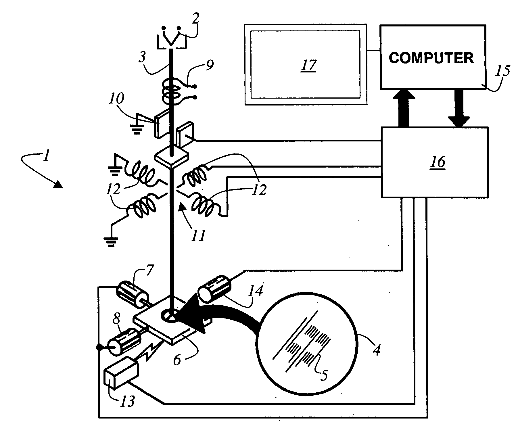
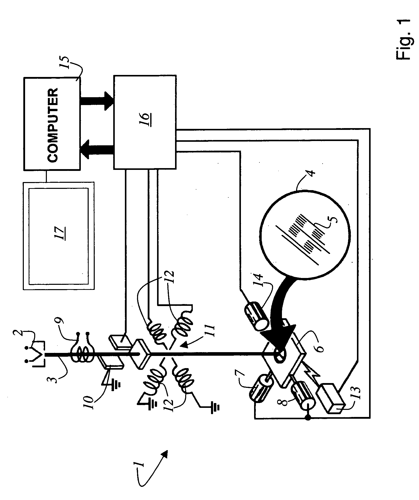
[0059]FIG. 1 shows a block diagram of an e-beam lithographic system 1. The e-beam lithographic system 1 has source of electrons 2 which emits an e-beam 3. The specification mentions the use of an e-beam 3 only. Nevertheless, it has to be understood that the invention is not limited to e-beams only. The invention can be used with particle beams in general, which are applicable to write a pattern 5 on substrate 4. The substrate 4 itself is placed in stage 6 which can be moved by motors 7 and 8 in a plane which is spanned by the X-coordinate X and the Y-coordinate Y. The e-beam 3 passes beam alignment coil 9 after the emerge from the e-beam source 2. After the beam alignment coil 9, in the direction of e-beam 3 propagation, a beam blanking unit 10 is provided. After that the e-beam 3 reaches a magnetic deflection unit 11, which comprises in general four magnetic coils 12. After that the e-beam 3 is directed to the substrate 4. As already mentioned the substrate 4 is positioned on the s...


PUM

PropertyMeasurementUnit
primary energyaaaaaaaaaa
widthaaaaaaaaaa
widthaaaaaaaaaa

Abstract

Method for reducing the fogging effect in an electron beam lithography system wherein the exposure is controlled in order to obtain resulting pattern after processing which are conform to design data. A model for the fogging effect is fitted by individually changing at least the basic input parameters of the control function, the function type is chosen in accordance to the Kernel type used in the proximity corrector. The proximity effect is considered as well and an optimised set of parameters is obtained in order to gain a common control function for the proximity and fogging effect. The pattern writing with an e-beam lithographic system is controlled by the single combined proximity effect control function and the fogging effect control function in only one data-processing step using the same algorithms as are implemented in a standard proximity corrector.

Description

RELATED APPLICATIONS [0001] This application claims priority of the European patent applications EP 04 103 019.8 and EP 04 103 497.6 which are incorporated by reference herein. FIELD OF THE INVENTION [0002] The invention refers to process for controlling the proximity effect correction in an electron beam lithography system. The process is suitable for precise numerical determination of the proximity parameters of the Point Spread Function (PSF) for optimised controlling the proximity correction in the high-resolution electron beam lithography (EBL). BACKGROUND OF THE INVENTION [0003] The proximity effect parameters are specific numerical inputs to control an arbitrary Proximity-Effect correction software. This satisfies high Critical Dimension control “CD-control” requirements (depending on actual International Technology Roadmap for Semiconductors ITRS from International SEMATECH) as well as to compensate pattern bias in the Mask and / or Direct-Write working with Gaussian and / or Sh...

Claims


Application Information

Patent Timeline
Patent Type & Authority Applications(United States)
IPC IPC(8): G03C5/00H01J37/317
CPCB82Y10/00H01J2237/31769H01J37/3174B82Y40/00Y10S430/143
Inventor HUDEK, PETERBEYER, DIRKMELCHIOR, LEMKE
Owner VISTEC ELECTRON BEAM
Why Eureka
Try Eureka