Light emitting device, phosphor, and method for preparing phosphor

a light emitting device and phosphor technology, applied in the direction of discharge tube/lamp details, discharge tube luminescnet screens, gas-filled discharge tubes, etc., can solve the problems of short life, difficult to obtain sufficient life, and difficult to emit light with long wavelength sides in the visible light range, so as to improve thermal resistance, weather resistance and light resistance of phosphor, and reduce the adverse effects of each light emitting element.

Active Publication Date: 2006-01-05
NICHIA CORP
View PDF4 Cites 89 Cited by
  • Summary
  • Abstract
  • Description
  • Claims
  • Application Information

AI Technical Summary

Benefits of technology

[0059] According to the present invention, it is possible to provide a light emitting apparatus, and so on, with sufficient life even under operating condition as lighting. The reason is that coating a phosphor improves thermal resistance, weather resistance and light resistance of the phosphor, and in addition reduces adverse effects on each light emitting element in the light emitting apparatus due to the phosphor. Accordingly, it is possible to improve life not only for a phosphor but also for light emitting apparatus under operating condition as lighting.
[0060] Additionally, according to the present invention, it is possible to provide a nitride group phosphor, which has excellent thermal resistance and can emit light from the yellow to red range, and a light emitting apparatus, which has the nitride group phosphor.

Problems solved by technology

However, in conventional light emitting apparatuses, in the case of application for lighting, there is a problem that it is difficult to obtain sufficient life.
This may cause short life.
In addition, in the aforementioned light emitting apparatus which emits white light, it is difficult to emit light with long wavelength side in the visible light range.
Generally, when the reddish component increases, the light emission characteristic of light emitting apparatus deteriorates.

Method used


Image

  • Light emitting device, phosphor, and method for preparing phosphor
  • Light emitting device, phosphor, and method for preparing phosphor
  • Light emitting device, phosphor, and method for preparing phosphor

Examples


first embodiment

LIGHT EMITTING APPARATUS

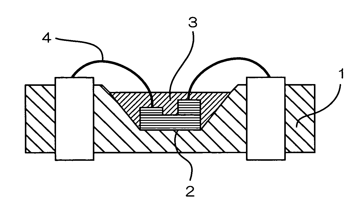
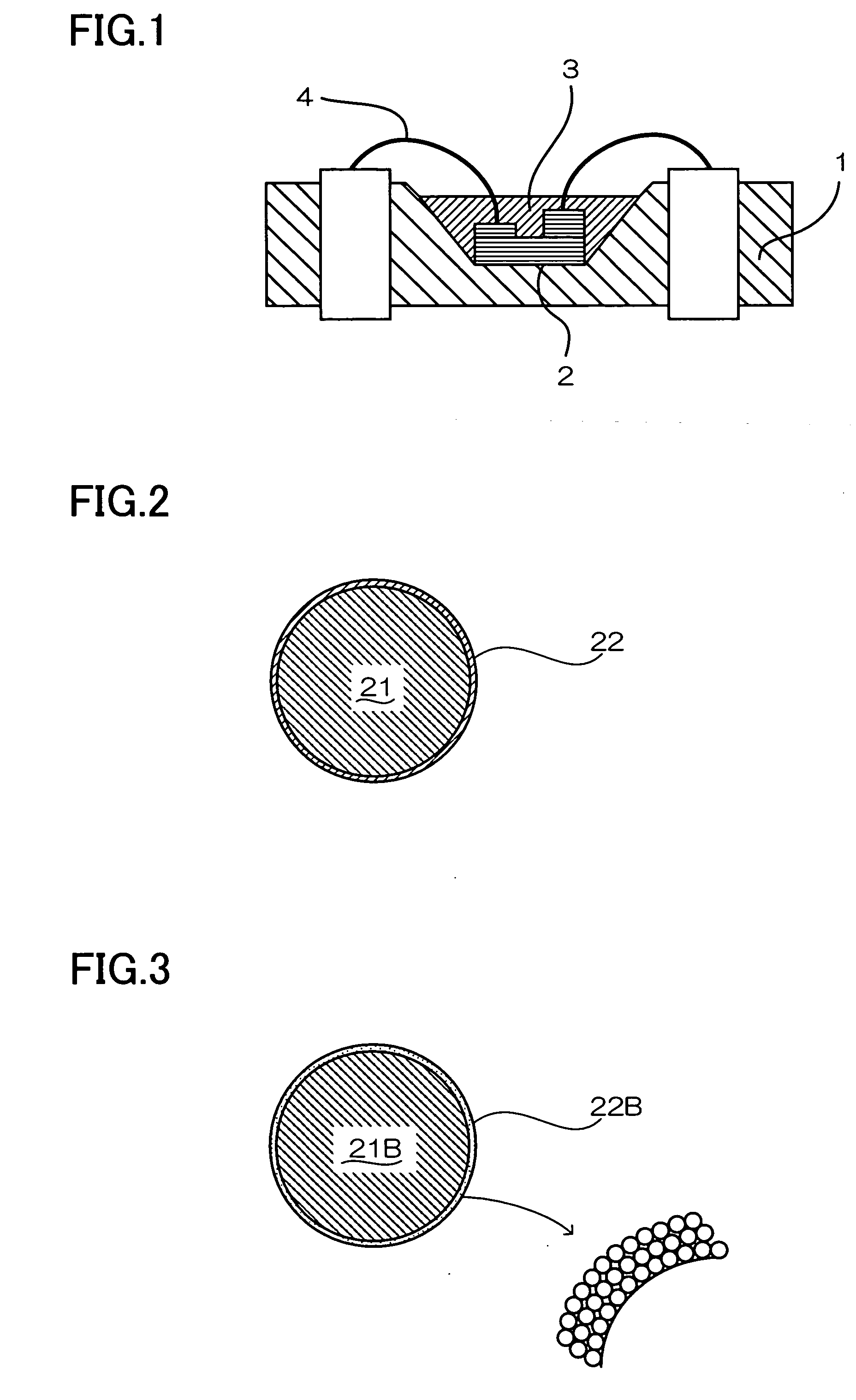
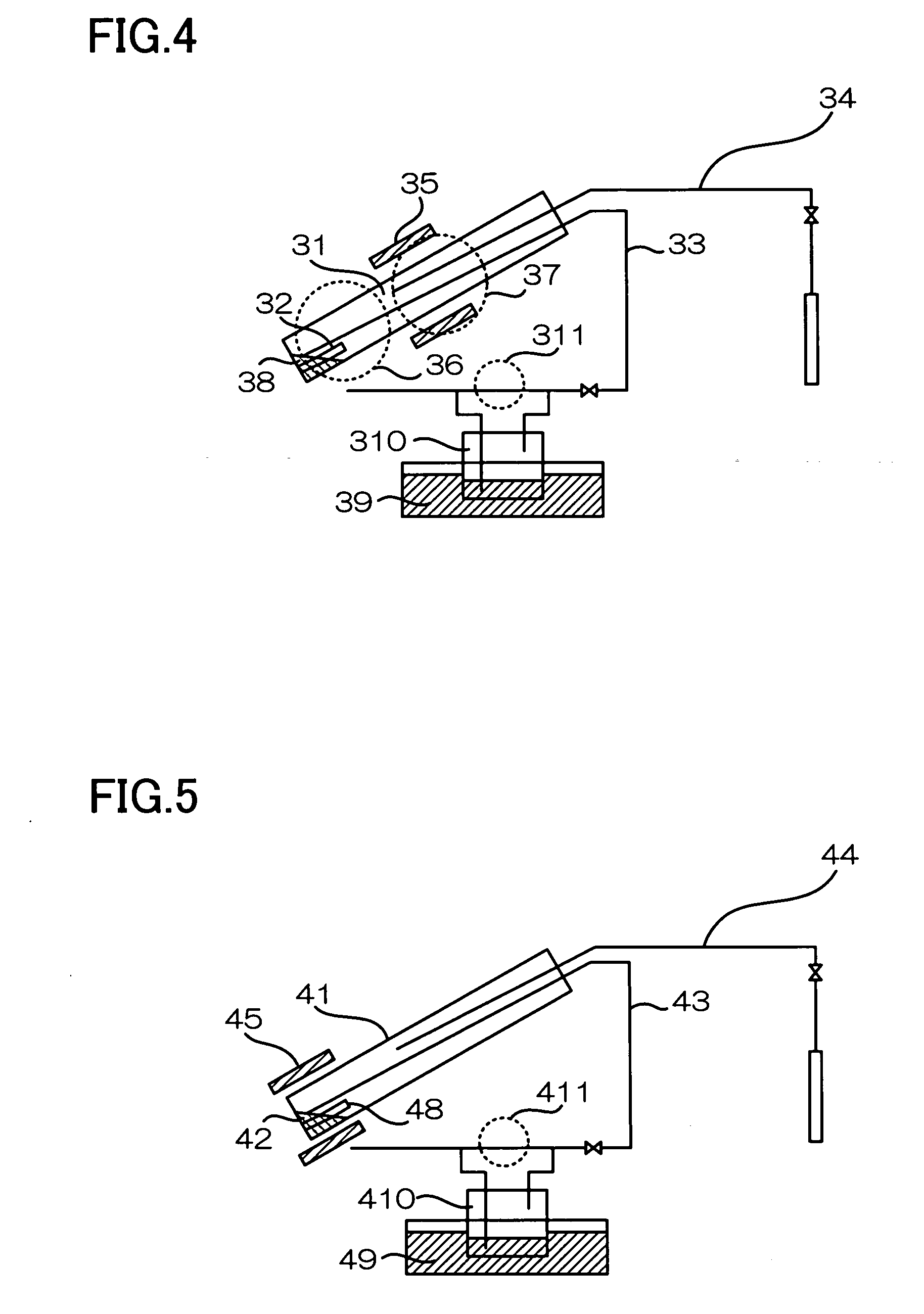
[0076]FIG. 1 is a schematic cross-sectional view of a light emitting apparatus according to a first embodiment of the present invention. FIGS. 2 and 3 are schematic cross-sectional views of phosphors. FIGS. 4 and 5 are schematic views of producing apparatuses for coating the phosphor.

Light Emitting Element

[0077] In this specification, light emitting elements include semiconductor light emitting elements, such as a light emitting diode (LED) and a laser diode (LD), and elements for emitting light by vacuum discharge or calorescence. For example, ultraviolet rays by vacuum discharge or the like can be used as a light emitting element. In the first embodiment of the present invention, a light emitting element with wavelength 550 nm or less, preferably 460 nm or less, and more preferably 410 nm or less is used. For example, an ultraviolet light LED which emits light with wavelength of 250 nm to 365 nm as ultraviolet light, or a high-pressure mercury lamp with ...

second embodiment

LIGHT EMITTING APPARATUS

[0086]FIG. 10 shows a light emitting apparatus according to a second embodiment. This light emitting apparatus has a light emitting element 10, a nitride group phosphor 11a which includes a nitride group phosphor material represented by L-M-N:R or L-M-O-N:R (where L contains at least one element selected from the group consisting of Be, Mg, Ca, Sr, Ba, and Zn, M contains at least one element selected from the group consisting of C, Si, Ge, Sn, Ti, Zr, and Hf, N is nitrogen, O is oxygen, and R is a rare earth element) and a coating material containing an N element for coating the nitride group phosphor material, and a phosphor member 11 composed of a transparent material 11b which includes the nitride group phosphor 11a.

[0087] The light emitting element 10 composed of an LED, for example, is mounted in a substantially central part of a cup disposed on the upper part of a mount lead 13a by die-bonding. The electrodes formed in the light emitting element 10 are...

third embodiment

[0142] With reference to FIG. 13, a light emitting apparatus according to a third embodiment of the present invention is now described. A phosphor member used for the light emitting apparatus according to the third embodiment is same as the phosphor member in the second embodiment. Since the difference in the light emitting apparatus according to the second embodiment is only the structure of the light emitting apparatus, only the structure of the light emitting apparatus according to the third embodiment will be described herein.

[0143] A light emitting element 101, which has an InGaN group semiconductor layer with light emission peak of 460 nm in the blue range as a light emitting layer, is used. A p-type semiconductor layer and an n-type semiconductor layer (not shown) are formed in the light emitting element 101. The conductive wires 104 connected to lead electrodes 102 are formed on the p-type semiconductor layer and the n-type semiconductor layer. An insulating mold material 1...


PUM

PropertyMeasurementUnit
thicknessaaaaaaaaaa
temperatureaaaaaaaaaa
wavelengthaaaaaaaaaa

Abstract

The surface of a phosphor is coated with a coating member made of a material different from the phosphor in chemical vapor-phase reaction. The coating member is made of any of metal oxide, metal nitride and metal oxynitride. The coating member coats the surface of the phosphor whereby having a substantially smooth film, or is formed such that a large number of fine particles relatively smaller than the phosphor aggregate to coat the whole surface of the phosphor. The coating member contains at least one metallic element selected from the group consisting of Al, Si, and rare earth elements. In addition, the phosphor is a transparent water-soluble phosphor and is an alkaline-earth silicon-nitride phosphor, an alkaline-earth silicon oxynitride phosphor, or the like. The BET value of the coated phosphor is 1.0 to 10 times the BET value before coating. The average thickness of the coating is 10 nm to 500 nm.

Description

TECHNICAL FIELD [0001] The present invention relates to a light emitting apparatus including a light emitting element and a phosphor which converts the wavelength of light emitted from the light emitting element, a phosphor for a light emitting element, and a method for producing a phosphor. The present invention particularly relates to a light emitting apparatus including a semiconductor light emitting element, such as LED and LD, for example, and a nitride group phosphor which absorbs a part of light emitted from the light emitting element and converts it into light with wavelength different from the absorbed light. BACKGROUND ART [0002] A light emitting apparatus has a structure for obtaining various types of chromaticity, such as white light, with a light emitting element which emits primary light, and a predetermined phosphor which absorbs a part of the primary light and emits secondary light the wavelength of which is longer than the primary light (for example, Patent Document...

Claims


Application Information

Patent Timeline
Patent Type & Authority Applications(United States)
IPC IPC(8): H01J11/02C09K11/08C09K11/77H01L33/50
CPCC09K11/0883C09K11/7734H01L33/502C09K11/7792C09K11/7735H01L2224/48091H01L2224/48247H01L2224/48257H01L2224/49107C09K11/77347H01L2924/00014
Inventor MARUTA, TADASHITAMAKI, HIROTO
Owner NICHIA CORP
Why Eureka
Try Eureka